Biomedical Engineering Reference
In-Depth Information
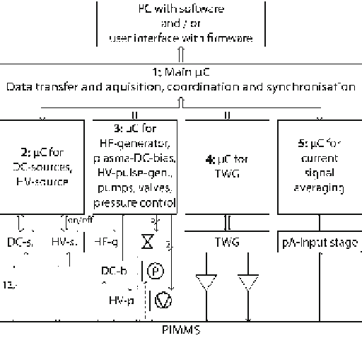
Fig. 28
Present topology of electronic components
ADCs for the DC-sources, the averaging stage for the current measurement, and the
user interface.
The realized topology is shown in Fig.
28
. Five firmware components are neces-
sary in this configuration. The tasks of the components 2-5 were described in previ-
ous sections. With the exception of averaging microcontroller (mC) for the current
measurement, all firmware components are implemented in C on standard general
purpose microcontrollers. The averaging mC is a CPLD (Complex Programmable
Logic Device) and is programmed in Verilog. The main mC serves as a coordinating
unit. It responds to user requests from a PC and/or user interface, assembles states
of other components, processes data, and transfers them between components and
PC. During the measurements it also synchronizes the involved components. For
communication between the microcontrollers an SPI-Bus (Serial Peripheral
Interface) is used. PC and main mC communicate via USB. The software presently
implemented on the PC is of experimental character. It was designed to evaluate the
performance of the different chip designs and to determine the optimum operational
conditions and their settings. It comprises a graphical user interface, which enables
fast access to all settings of the setup and the measurement of variations and spectra.
Furthermore, a script language is integrated into the software, which allows to cre-
ate customized sequences, protocols, and automatic benchmarking of the results, as
well as mathematical post processing of measured spectra.