Biomedical Engineering Reference
In-Depth Information
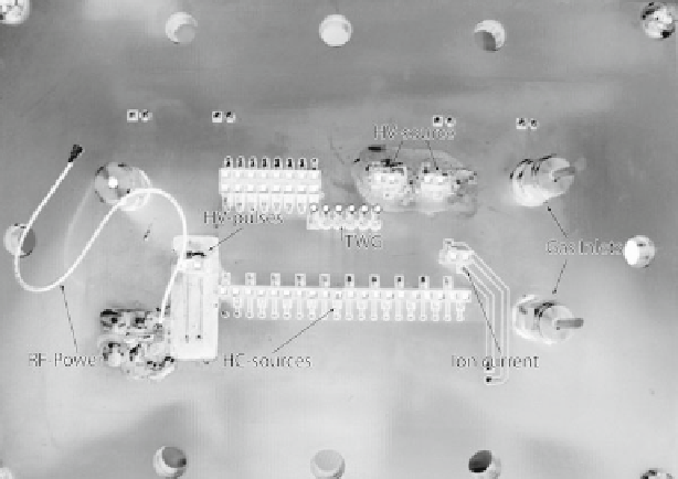
Fig. 24
The vacuum seal and electrical contact vias through the PCB
For a mass range of 1
m/z
to ca. 1,200
m/z
a frequency range for the pulse train of
250-5 MHz is needed for the actual chip design.
Ramp time of the staircase shaped frequency change has to be <1 ms.
For the desired mass resolution the frequency resolution has to be better than
100 Hz.
For the optimization steps for the ion extraction, as described in Sect.
6.3
, all
generator signals have to be set to 0 V.
As the broadband rectangular signals cannot be matched to the impedance of the
finger electrodes, the TWG has to be placed physically close to the evacuated
PIMMS-chip and the signals tracks to the chip have to be as short as possible.
However, the generator cannot be placed into the vacuum chamber, e.g., because of
insufficient heat dissipation. In the present concept a PCB, as shown in Fig.
24
,
serves as both the vacuum seal and via for the electronics within and outside the
vacuum chamber. Thus, the critical signal tracks are reduced to few millimeters. In
future an appropriate vacuum tight housing of the chip will meet this demand even
more effectively, as the driving stages of TWG can be placed directly next to the
chip housing on the PCB.
In an early version a more complex TWG with four variable phase shifted signals
with controllable duty cycle [
34
] was investigated, primarily to determine the opti-
mum signal shape driving the SIS-Separator. From these results the actual version
was derived, which due to the concentration of the electronics and signals to the
inevitable functions can be minimized with respect to size, cost, and power con-
sumption even further. Still a generator-PCB circuit of 10 × 5 cm² (Fig.
25a
) appears
rather large as compared to the PIMMS-Chip.