Biomedical Engineering Reference
In-Depth Information
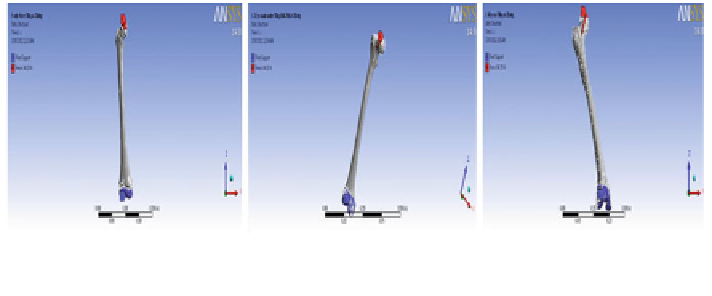
Model 1
Model 2
Model 3
Fig. 7
Half of 70 and 75 kg loads acting on the head of right proximal femurs at 28
Finite Element Analysis
The 3D Finite Element Models of femur bone of all male patients with volumetric
mesh and realistic material assigned are imported into ANSYS v14. Since the
femur bone models are nonlinear, asymmetric, and curved in all three planes,
the models are first imported in Finite Element Modeler and initial geometry are
created for each model, then transferred individually to static structural module in
ANSYS 14 for FEA. Three-dimensional FE models of human femur bone with
realistic material properties are analyzed in static structural workbench of ANSYS
14 capabilities. The boundary conditions discussed below are applied to each
model for the investigation of total deformation, equivalent Von-Mises stress
distribution, maximum principal stress distribution, and fatigue tool throughout the
whole femur and the results compared.
Boundary Conditions
Femur being a thigh bone shares the whole body weight equally by both the left
and right femurs. In our study, the varying body weights of 70 kg (686.7 N) and
75 kg (735.75 N) are considered to be equally shared by both femurs according to
the hip mechanism. Thus, load of 343.35 N and 367.875 N which is half the whole
body weight is applied on the right femur head of every model at a constant angle
of 28 [
11
,
21
-
23
] without consideration of muscle forces to resist the bending
stress produced in all the models during load application and a fixed support is
provided at lateral condyle, medial condyle, and patellar surface in every model;
thus, the femur is assumed to be a cantilever beam with one end fixed and the other
end subjected to load. The boundary conditions are shown in Fig.
7
.
Search WWH ::

Custom Search