Biomedical Engineering Reference
In-Depth Information
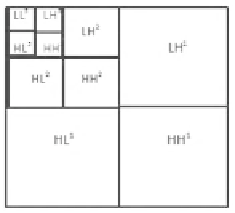
Fig. 2 Wavelet decomposition: 1, 2, 3 decomposition levels, H high frequency bands, L low
frequency bands
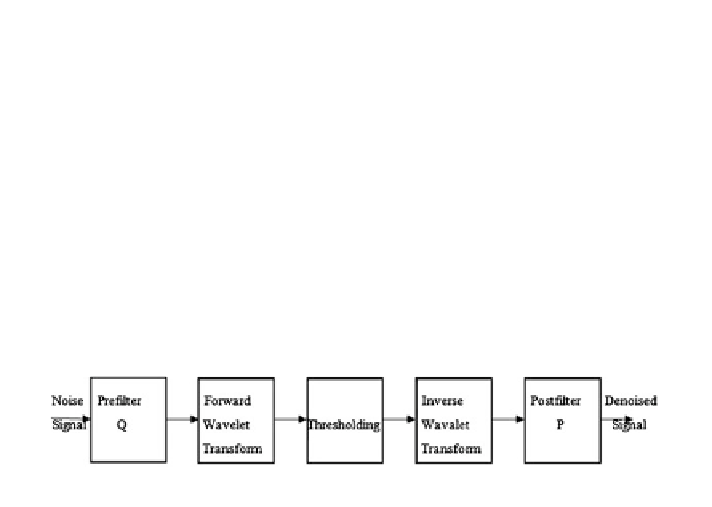
Fig. 3
Denoising by wavelet domain
components. The successive analysis of the low pass component only is called
wavelet decomposition, (Fig.
1
b), whereas the analysis of both the low and high
pass components is called wavelet packet decomposition; the existence of small
coefficients is more likely to be due to the noise contamination, whereas the large
coefficients contain significant image details. Hence, the small magnitude coeffi-
cients may be thresholded without affecting the large ones and therefore the
quality of the image [
8
].
The investigations show that themethod for denoising differs only in the
selection of the wavelets and their decomposition levels [
6
].
The algorithm has the following steps:
1. Calculate the DWT of the image.
2. Threshold the wavelet coefficients (Threshold may be universal or subband
adaptive).
3. Compute the IDWT to get the denoised estimate.
Wavelet transform of noisy signal should be taken first and then thresholding
function is applied on it. Finally the output should be undergone inverse wavelet
transformation to obtain the estimate x as shown in Fig.
3
.
The DWT of any signal sample is given by Eq. (
7
)
S
DWT
j
; ðÞ¼
X
N
1
a
¼
2
j
;
s
¼
k2
j
S
nj
;
k
w
n
;
ð
7
Þ
n
¼
0
Search WWH ::

Custom Search