Biomedical Engineering Reference
In-Depth Information
t=11s
a)
t=0s
t=5.5s
t=16.5s
Group 1
1mm
1mm
1mm
1mm
b)
t=0s
t=11s
t=22s
t=33s
1mm
1mm
1mm
1mm
Group 2
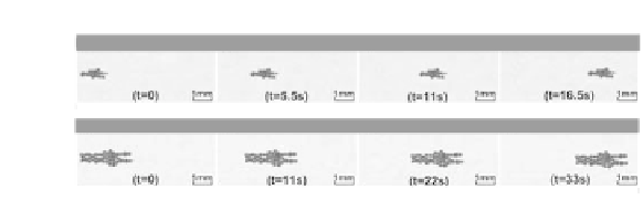
Figure 8.38
Motion images of MSP cluster at different time: (a) Displacement
of Group 1, (b) Displacement of Group 2.
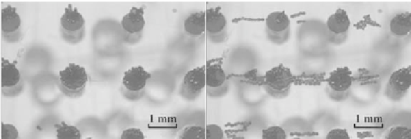
Magnetized MSPs aggregated in cylindrical steel areas of the
patterning device to form self-assembled dot pattern due to the
stronger distribution of magnetic lux density. We compare the
MSPs pattern between before and after exposing the pattern in
the gradient magnetic ield as illustrated in Fig. 8.39, the interval
between two dots is illed with MSPs at the magnetic ield gradient
direction, which improves the pores interconnection among different
dots. After the removal of permanent magnet, MSP can still keep the
pattern shape and be further used for fabrication of scaffold with
the method mentioned in [51], and dot pattern on the scaffold is
shown in Fig. 8.40. The scaffold shows controllable diameters and
appropriate interconnection of pores, elegant pore wall morphology
and high porosity in small-size scaffolds. This sheet-like scaffold
can be further used for fabricating tubular scaffold by welding the
boundary of inner and outer sheet of scaffold with original polymer
solution (PLCL 10
w% in chloroform) as described in [51].
1mm
1mm
a)
b)
Figure 8.39 (
a) Dot pattern of magnetically-guided self-assembled MSPs.
(b) Self-assembled MSPs under motion evaluation system, the
interval between two dots illed with MSPs at the gradient
magnetic ield direction.
Therefore, these results indicate that the proposed method
suggests the feasibility of steering MSP/MSP cluster in hexane


Search WWH ::

Custom Search