Biomedical Engineering Reference
In-Depth Information
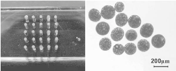
A neodymium magnet (surface magnetic lux density is 0.035
T)
is placed under the patterning device as shown in Fig. 8.36(a). The
magnetic lux density is larger near the cylindrical steel area with
maximum value of magnetic lux density at their axial directions is
48.6
mT when a neodymium magnet with the surface magnetic lux
density of 0.4
T is placed under the patterning device. Magnetized
MSPs aggregated in these areas and form assembled dot pattern.
Contrast experiment was conducted between before and after
exposing the pattern in the gradient magnetic ield to evaluate
the effectiveness of our proposed method in improving the pore
interconnection among different pores. This pattern is chosen
under the consideration that about 20 MSPs can aggregate on the
steel area for MSPs motion control experiments. Figure 8.36(b)
shows the optical microscope image of MSPs with controlled
diameter. Commercially available magnetic powder is used in this
fabrication as encapsulated particles. Compared with traditional
magnetic particles of ribbon shape, the magnetic powder used is
isotropic spherical structure, has a mean diameter of 1-10
μm and
a maximum residual magnetic lux density of 835-865
mT after
magnetization. These MSPs are with the size range of 160-200
μm
and the magnetic powders inside possess a residual magnetic lux
density of 36.6
mT after magnetized by a permanent magnet whose
surface magnetic lux density is 0.4
T. MSPs are divided into two
groups with different quantity before magnetization for the motion
evaluation experiment.
MSP
Steel
Rod
PMMA
Magnet
200m
a)
b)
Figure 8.36
(a) Patterning device over a magnet. with a (PMMA thickness
5
mm, steel rods diameter 0.7
mm, distance between rods 3
mm). (b) Optical microscope image of MSPs.


Search WWH ::

Custom Search