Biomedical Engineering Reference
In-Depth Information
transformation matrix. That way 670 frames obtained from the scan
of the blood vessel model were processed. A three-dimensional model
was built after assigning 3D coordinates to the pixels identiied as
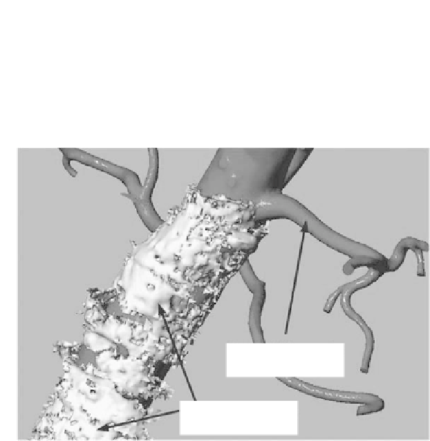
part of the blood vessel boundary. Figure 7.27 compares 3D imaging
of the blood vessel model constructed using the hybrid probe with
the stereo-lithographic data used to build the silicone model.
Stereo-Lithographic
Data
3D Imaging from
Sensor Fusion
Figure 7.27
3D imaging result for the sensor fusion between magnetic
tracker and intravascular ultrasound. 3D rendering for a
section of vasculature membrane that corresponds to 670
video frames, is compared with the stereo-lithographic data
used for constructing the silicone model.
7.5.6 ErrorMeasurement
For measuring the imaging accuracy, we used a block model of the
same vascular structure. The rigid structure of this model enables
comparing the 3D imaging of the hybrid probe to the stereo-
lithographic (STL) data used for constructing the silicone models.
Error was measured by comparing eight points distributed uniformly
along respective cross sections of STL data with experimental data.
Five corresponding cross sections were selected (Fig. 7.28); the
difference between them was averaged at eight locations distributed
uniformly around the contour. The maximum error is 1.2 mm and
minimum error is 0.735 mm (Fig. 7.29).


Search WWH ::

Custom Search