Biomedical Engineering Reference
In-Depth Information
(,
012
(7.6)
0
n
corresponds to the reciprocation of the camera (DOF1),
C
1
n
to the tilt angle of the camera (DOF2) and
C
2
n
to the panning angle of
the camera (DOF3) (Fig. 7.3). The detection range
d
n
must be equal
or bigger than the arterial model cross section diameter to ensure
that the reference points
P
n
are detected when the catheter shaped
sensor passes through the arterial model. Therefore even if the
maximum cross section diameter of the lumen of the arterial model
is of 6 mm, the detection range was set to 10 mm. This gives time
to the robotic system to place the camera at the correct location on
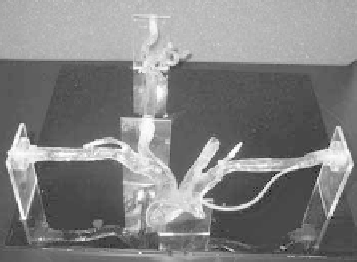
time. With the silicone model placed inside the robotic camera work
space, 7 sets of spatial coordinates were collected using the sensor
inside of it (Fig. 7.6). Then, each set of coordinates was associated
with a different coniguration
C
of the robotic camera, building
that way each vector of
M
0
. The coniguration for each vector was
designed in order to keep the catheter inside the ield of view of the
camera at all times.
PpppCCC
,
,
,
,
)
n
xnynznnnn
Reference point
Silicone Model
of Vasculature
0.8
P
6
0.6
Coronal
Axis
Sagital
Axis
P
5
0.4
P
4
0.2
P
3
0
P
2
-0.2
P
1
-0.4
P
0
-0.6
-0.8
a)
b)
P
0
P
1
P
2
P
3
P
4
P
5
P
6
Reference Points
Figure 7.6
(a) Reference points inside silicone model of vasculature for
robot manipulation experiment. (b) Dispersion of samples of
the magnetic tracker at those locations.
In this experiment, the 3DOF of the camera were set to change
automatically according to the software map
M
0
. The control diagram
is shown in Fig. 7.7.
For the reference points
P
n
the maximum registered dispersion
was 0.80 mm (Fig. 7.6). This allows the usage of those reference
points to apply the control technique for
M
0
as the detection range
is of 10 mm. A PC was used to interface the robotic camera and the


Search WWH ::

Custom Search