Biomedical Engineering Reference
In-Depth Information
6.4 Stress Measurement
Images
N
0
and
N
1
are shown in Figs. 6.10(a) and 6.10(b), respectively.
N
1
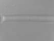
shows an optical path length between 640 and 840
μ
m for the
55% of pixels, and 13.4% of pixels of
N
1
have a shorter optical path
length. Images
N
2
and
N
3
are shown in Figs. 6.10(c) and 6.11,
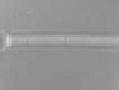
I
G
min
= 53 and
I
G
max
= 221. The threshold of 20
μ
m was adequate and no
black pixels appeared in the image area corresponding to blood
vessels. Background noise has nearly disappeared. After analyzing
N
2
we obtained
N
a
2
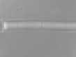
, we measured that the 98.2% of pixels of
N
2
had
(
T
)
(
x, y
)
below 32 kPa (Fig. 6.10(d)). Results for all the analyzed
images are summarized in Table 6.1 and shown in Figs. 6.11 and
6.12. Estimated low pressure variation during registration of
F
is
shown in Fig. 6.9.
-
T
1
2
[mm]
>2.55
1.92
1.28
0.64
0
b)
a)
[k
P
a]
>128
96
64
32
0
c)
d)
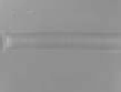
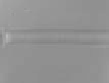
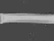
Figure 6.10
Images used and obtained during the calibration process (a)
image
N
0
, used to calculate the optical path length. (b)
N
1
optical path length quantiication. (c) Image
N
2
used to ind
I
G
min
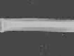
, and (d)
N
a
2
stress quantiication of
N
2
.
[kP
a
]
>128
F
0
F
1
F
2
F
3
F
4
96
64
32
0
F'
0
F'
1
F'
2
F'
3
F'
4
Time
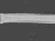
Figure 6.11
F
image collection and their respective stress measurements
F
a
.
N
3
=
F
3
is the image used to ind
I
G
max
during the calibration
process.


Search WWH ::

Custom Search