Biomedical Engineering Reference
In-Depth Information
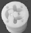
Hybrid Pump Extruded View
Frontal
Cover
Static
Casing
Hollow
Shaft
Drive Gear
Lobes
Front View
Main Shaft and
Bearing
Synchronization
Gears
Static
Casing
Lobes
Figure 6.5
Mechanism inside the piston-lobe pump. Hollow shaft couples
the lobe pump to the reciprocation and rotational motions.
6.1.2
Feedback Control
Feedback control was applied in two closed loops for controlling
reciprocation frequency and pressure in the pump output, the
diagram of the system is shown in Fig. 6.6. Command signal
F
(
z
)
is
a step function with the desired frequency, and
P
(
z
) is a polynomial
approximation of the blood pressure reported in [10].
A
,
L,
and
Pi
are transfer functions of the accumulator; lobe pump and piston
pump, C
1
and C
2
are PI type controllers. Function
P
(
z
) is periodical
and synchronized with the reciprocation cycle repeated every 2500
steps. When accumulator volume reaches its minimum, an optical
switch state change marks the start of the reciprocation cycle,
P
(
z
)
is deined as follows:
If
z
<
1250
18
6
14
5
10
4
s
s
s
Pz
(
)
7.25
10
z
6.59
10
z
2.61
10
z
s s s
(6.5)
73
42
2
4.25
10
z
3.1
10
z
4.3
10
z
152.5


Search WWH ::

Custom Search