Biomedical Engineering Reference
In-Depth Information
700
400
350
L1
L2
350
600
300
L3
L4
L5
Reference
300
500
250
250
400
200
200
L1
L2
300
150
L3
L4
150
L5
Reference
L1
L2
200
100
L3
L4
100
L5
Reference
100
50
50
0
0
0
0
0.2
0.4
0.6
0.8
1
0
0.2
0.4
0.6
0.8
1
0
0.2
0.4
0.6
0.8
1
Normalized Time [-]
Normalized Time [-]
Normalized Time [-]
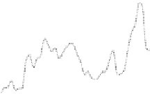
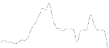
Figure 4.28
Catheter tip position in the three axes in normalized time for
trajectories
L
1
-L
5
and the obtained reference trajectory.
800
1200
Reference XZ
L1
700
L2
L3
1000
L4
L5
600
800
500
400
600
300
400
200
Reference XY
L1
200
100
L2
L3
L4
L5
0
0
0
0.2
0.4
0.6
0.8
1
0
0.2
0.4
0.6
0.8
1
Normalized Time [-]
Normalized Time [-]
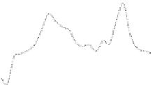
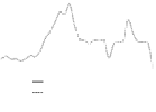
Figure 4.29
Blood vessel wall deformation in normalized time for
trajectories
L
1
-L
5
and the obtained reference trajectory.
10
5
9
4.5
8
4
7
3.5
6
3
5
2.5
4
2
Reference XZ
L1
3
1.5
L2
L3
Reference XY
L1
2
L4
L5
1
L2
L3
L4
L5
1
0.5
0
0
0
0.2
0.4
0.6
0.8
1
0
0.2
0.4
0.6
0.8
1
Normalized Time [-]
Normalized Time [-]
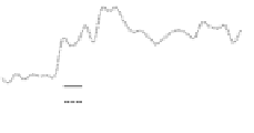
Figure 4.30
Stress level in normalized time for trajectories
L
1
-L
5
and the
obtained reference trajectory.
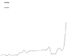
The reference trajectory construction method was applied in
a mono-vision coniguration to compare the catheter motion and
stress levels variation of reference trajectory with trajectories
while the catheter was driven by inexperienced human and robot.


Search WWH ::

Custom Search