Biomedical Engineering Reference
In-Depth Information
h
(
t)
H
(
)
ω
Passband
1
Stopband
Stopband
0
0
−
w
c
w
c
ω
t
2
π
/
/
W
c
(a)
(b)
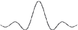
FIGURE 11.18
Time and frequency domain representation of the ideal
low-pass filter. (a) The impulse
response of the ideal low-pass filter,
h
(
t
). (b) Transfer function of the ideal low-pass filter,
H
(o).
transfer function and the input Fourier transform (Eq. (11.35)).Theimpulseresponseand
transfer function of the ideal low-pass filter are shown in Figure 11.18. The transfer func-
tion of this filter takes a value of one within the filter passband and zero within the
stopband.
Since the output of a linear system in the frequency domain is given as the product
of the input Fourier transform and the signal transfer function,
,
any signal presented to this filter within its passband will pass through to the output
uninterrupted because the frequency components are multiplied by one. In contrast,
signals in the stopband are removed at the output of the filter, since the frequency
components are multiplied by zero. The impulse response of the ideal low-pass analog
filter is
Y
ð
o
Þ¼
H
ð
o
Þ
X
ð
o
Þ
h
LP
ð
t
Þ¼
W
c
p
sinc
ð
W
c
t
Þ:
ð
11
:
36
Þ
where
is the filter cutoff frequency. In the frequency domain, the ideal low-pass
filter transfer function is
W
c
¼
2p
f
c
1
0
jj<
W
c
o
o
H
LP
ð
o
Þ¼
jj>
W
c
:
ð
11
:
37
Þ
This dual time and frequency domain representation of the ideal low-pass filter is shown in
Figure 11.18. Note that the transfer function takes a value of one only within the passband.
At the cutoff frequency, the filter transfer function transitions from a value of one in the
passband to a value of zero in the stopband.
In the frequency domain, the ideal high-pass filter performs the exact opposite function
of the low-pass filter
0
1
jj<
W
c
o
o
H
HP
ð
o
Þ¼
,
ð
11
:
38
Þ
jj>
W
c
that is, the passband exists for frequencies above the cutoff frequency, whereas the
stopband exists for frequencies below the filter's cutoff. This filter therefore preserves
high-frequency signal components (above the cutoff frequency) and selectively removes
low-frequency signals. The ideal high-pass filter transfer function can be easily derived
from the ideal low-pass filter as
H
HP
ð
o
Þ¼
1
H
LP
ð
o
Þ
ð
11
:
39
Þ


