Biomedical Engineering Reference
In-Depth Information
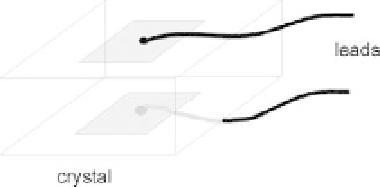
FIGURE 10.17
Ultrasonic transducer.
where
is a proportionality constant for the specific piezoelectric material. By assuming
that the piezoelectric crystal acts like a parallel plate capacitor, the voltage across the crys-
tal,
k
V,
is given by
D
V
¼
D
Q
C
ð
10
:
14
Þ
where
C
is the equivalent capacitance of the crystal.
EXAMPLE PROBLEM 10.10
Derive a relationship for calculating the output voltage across a piezoelectric transducer that
has a thickness,
d,
and area,
A
, in terms of an applied force,
F
.
Solution
The capacitance of a piezoelectric transducer can be approximated by Eq. (10.12). Equation (10.14)
is combined with the relationship given by Eq. (10.13) to give
D
V
¼
D
Q
C
¼
k
F
C
¼
k
F
d
e
0
e
r
A
Since the crystal has an internal leakage resistance, any steady charge produced across its
surfaces will eventually be dissipated. Consequently, these piezoelectric transducers are not
suitable for measuring a steady or low-frequency DC force. Instead, they are used either as
variable force transducers or as mechanically resonating devices to generate high frequen-
cies (typically from 1 to 10 MHz) either in crystal-controlled oscillators or as ultrasonic
pulse transducers.
Piezoelectric transducers are commonly used in biomedical applications to measure the
thickness of an object or in noninvasive blood pressure monitors. For instance, if two simi-
lar crystals are placed across an object (e.g., a blood vessel), one crystal can be excited to
produce a short burst of ultrasound. The time it takes for this sound to reach the other
transducer can be measured. Assuming that the velocity of sound propagation in soft tis-
sue,
, it takes the ultrasonic pulse to propagate
across the object can be measured and used to calculate the separation distance,
c
t
, is known (typically 1500 m/s), the time,
t
d
, of the
two transducers from the following relationship:
d
¼
c
t
t
ð
10
:
15
Þ