Biomedical Engineering Reference
In-Depth Information
S
V
V
P
S
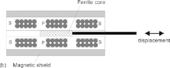
Ferrite core
(a)
FIGURE 10.9
LVDT transducer: (a) an electric diagram and (b) a cross-section view.
polarity in order to achieve a wider linear output range. The mutual inductance coupled
between the coils is changed by the motion of a high-permeability slug. The primary coil
is usually excited by passing an AC current. When the slug is centered symmetrically with
respect to the two secondary coils, the primary coil induces an alternating magnetic field in
the secondary coils. This produces equal voltages (but of opposite polarities) across the two
secondary coils. Therefore, the positive voltage excursions from one secondary coil will can-
cel out the negative voltage excursions from the other secondary coil, resulting in a zero net
output voltage. When the core moves toward one coil, the voltage induced in that coil is
increased proportionally to the displacement of the core, while the voltage induced in the
other coil is decreased proportionally, leading to a typical voltage-displacement diagram,
as illustrated in Figure 10.10. Since the voltages induced in the two secondary coils are
out of phase, special phase-sensitive electronic circuits must be used to detect both the posi-
tion and the direction of the core's displacement.
Electromagnetic Flow Transducer
Blood flow through an exposed vessel can be measured by means of an electromagnetic
flow transducer. It can be used in research studies to measure blood flow in major blood
vessels near the heart, including the aorta at the point where it exits from the heart.