Biomedical Engineering Reference
In-Depth Information
Kirchhoff's Voltage Law
Kirchhoff's voltage law (KVL) states that the sum of all voltages in a closed path is zero, or
N
1
v
n
ð
t
Þ¼
0
ð
9
:
5
Þ
n
¼
where there are
denoting the
individual voltage drops. The sign for each voltage drop in Eq. (9.5) is the first sign encoun-
tered while moving around the closed path.
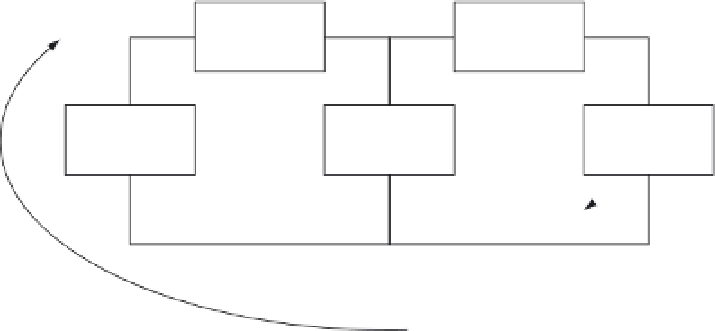
Consider the circuit in Figure 9.8, with each circuit element assigned a voltage,
N
voltage drops assigned around the closed path, with
v
n
(t)
, with a
given polarity and three closed paths, CP1, CP2, and CP3. Kirchhoff's voltage law for each
closed path is given as
v
n
CP1
:
v
3
þ
v
1
þ
v
4
¼
0
CP2
:
v
4
þ
v
2
þ
v
5
¼
0
CP3
:
v
3
þ
v
1
þ
v
2
þ
v
5
¼
0
Kirchhoff's laws are applied in electric circuit analysis to determine unknown voltages and
currents. Each unknown variable has its distinct equation. To solve for the unknowns using
MATLAB, we create a matrix representation of the set of equations and solve using the
techniques described in the appendix. This method is demonstrated in many examples in
this chapter.
9.3.4 Power and Energy
Power is the rate of energy expenditure given as
p
¼
dw
dt
¼
dw
dq
dt
¼
vi
ð
9
:
6
Þ
dq
+
v
1
-
+
v
2
-
CP3
Circuit
Element
Circuit
Element
CP1
CP2
+
v
3
-
+
v
4
-
+
v
5
-
Circuit
Element
Circuit
Element
Circuit
Element
FIGURE 9.8
Circuit illustrating Kirchhoff's voltage law. Closed paths are identified as CP1, CP2, and CP3.