Biomedical Engineering Reference
In-Depth Information
q
B
¼
K
1
q
B
¼
K
1
and therefore
K
2
q
A
:
Since
q
P
¼
K
1
q
B
, we eliminate
q
B
by substituting
K
2
q
A
,which
e
K
1
t
:
While quasi-steady-state assumes that reactant
gives
q
P
¼
K
q
A
and
q
P
¼
q
A
ð
0
Þ
1
1
B
is immediately in steady state and reac-
K
2
, in which
5
tant
A
creates product
P
directly, there is a period of time,
q
B
moves from 0 to
:
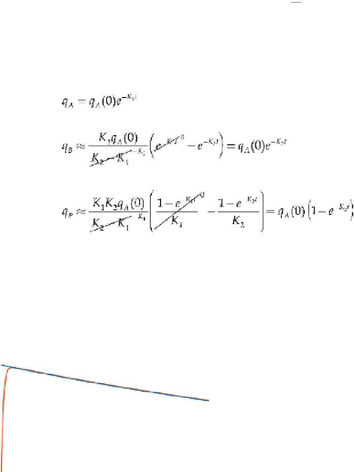
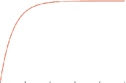
Figure 8.3 illustrates the approximation in Eq. (8.30), with the true solution for Eq. (8.29)
given with
K
1
K
1
K
2
q
A
:
Note also that steady state for reactant
B
is quite small and equals
K
2
q
A
q
A
ð
0
Þ¼
10,
q
B
ð
0
Þ¼
0and
q
P
ð
0
Þ¼
0,
K
1
¼
2, and
K
2
¼
500
:
For
q
B
, the approxima-
5
tion is quite accurate after it reaches quasi-steady-state,
t
¼
K
2
¼
0
:
01
:
For
q
P
, the approxi-
mation is quite accurate for the entire duration.
Now suppose
By a similar rational, the second reaction is now slower as
compared to the first reaction and is rate limiting. For the rate limiting second reaction,
an approximation to Eq. (8.29) for
K
1
K
2
:
e
K
1
t
q
B
and
q
P
is to eliminate the
term, since it goes to
e
K
2
t
zero almost immediately, as compared to the
term, giving
ð
8
:
31
Þ
Here, reactant
A
disappears almost immediately and reactant
B
increases almost immedi-
ately to
Þ:
Another way to look at this rate limiting reaction is to assume that reactant
q
A
ð
0
A
is in a
quasi-steady-state mode—that is
q
A
¼
0. From
q
A
¼
0 and Eq. (8.28), we have
q
A
¼
0 and
0.05
10
q
B
(Approx.)
0.04
8
0.03
6
q
B
(True)
0.02
4
0.01
2
0
0
0
0.05
0.1
0.15
0.2
0
1
2
3
4
5
Time
Time
FIGURE 8.3
A rate limiting sequential reaction for
K
1
. Note that both the approximation and true solution for
q
P
are drawn in the figure on the right.