Biomedical Engineering Reference
In-Depth Information
The dynamic response of each model can be quantified by applying a step change in
force
and noting the model's resulting change in length, or position
, denoted the
F
x
creep
response. The converse experiment applies a step change in
and measures the resulting
x
change in
. Creep and stress relaxation tests for each dynamic
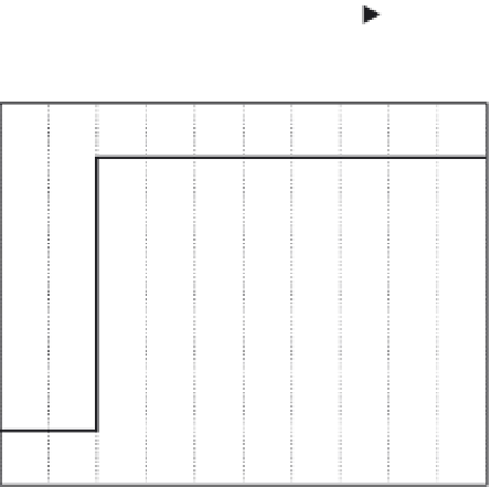
model can be carried out easily using the Simulink program. Figure 4.20 shows a purely
elastic material subjected to a step change in applied force
F
, denoted
stress relaxation
F
. The material's subsequent
position
follows the change in force directly. This material exhibits no creep. Figure 4.21
shows the purely elastic material subjected to a step change in position
x
x
. Again, the mate-
rial responds immediately with a step change in
(i.e., no stress relaxation is observed).
James Clerk Maxwell (1831-1879) used a series combination of ideal spring and dashpot
to describe the viscoelastic properties of air. Figure 4.22 shows the Maxwell viscoelastic
model subjected to a step change in applied force, and Figure 4.23 shows the Maxwell mod-
el's stress relaxation response. The latter exhibits an initial high stress followed by stress
relaxation back to the initial stress level. The creep response, however, shows that this
model is not bounded in displacement, since an ideal dashpot may be extended forever.
Woldemar Voight (1850-1919) used the parallel combination of an ideal spring and dash-
pot in his work with crystallography. Figure 4.24 shows the creep test of the Voight visco-
elastic model. Figure 4.25 shows that this model is unbounded in force. That is, when a step
change in length is applied, force goes to infinity, since the dashpot cannot immediately
respond to the length change.
F
Elastic Model
−
simple spring
1
1/K
Creep
F
x
6
5
4
3
2
1
0
−
1
0
0.5
1
1.5
2
2.5
3
3.5
4
4.5
5
Time t [s]
FIGURE 4.20
Simulink model of the creep test for a purely elastic material (an ideal spring). This model solves
the equation
x
¼
F/K
, where
x
is displacement,
F
is applied force, and
K
is the spring constant. Below is the elastic
creep response to a step increase in applied force
F
with
K
¼
1 and force changed from 0 to 5 (arbitrary units).
The displacement
x
linearly follows the applied force.


