Biomedical Engineering Reference
In-Depth Information
EXAMPLE PROBLEM 4.9
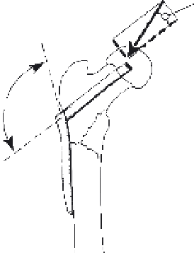
Figure 4.16 (left) shows an orthopedic nail-plate used to fix an intertrochanteric fracture. The hip
applies an external force of 400 N during static standing, as shown. The nail-plate is rectangular
stainless steel with cross-sectional dimensions of 10 mm (width) by 5 mm (height), and is well-fixed
with screws along its vertical axis and friction fit into the trochanteric head (along the
x
-axis). What
forces, moments, stresses, and strains will develop in this orthopedic device?
Solution
As for any statics problem, the first task is constructing a free-body diagram, including all
applied forces and moments and all reaction forces and moments that develop at the supports.
Because of the instability at the fracture site, the nail-plate may be required to carry the entire
400 N load. Consequently, one reasonable model of the nail-plate is a cantilever beam of length
0.06 m with a combined loading, as depicted in Figure 4.16 (right, top). The applied 400 N load
consists of both axial and transverse components:
400 Ncos 20
¼
F
x
¼
376 N
400 Nsin 20
¼
F
y
¼
137 N
y
400 N
20
F
y
A
x
x
F
x
M
a
A
y
0.06m
135
y
M
376N
N
x
x
V
8.22
Nm
137N
FIGURE 4.16
(Left) An intertrochanteric nail plate used in bone repair. To the right is the free-body
diagram of the upper section of this device, and below it is the free-body diagram of a section of this beam
cut at a distance
x
from the left-hand support.
Adapted from [2].
The axial load produces compressive normal stress; from Eq. (4.47),
s
x
¼
F
x
A
376 N
¼
Þ
¼
7
:
52 MPa
ð
0
:
005 m
Þð
0
:
01 m