Biomedical Engineering Reference
In-Depth Information
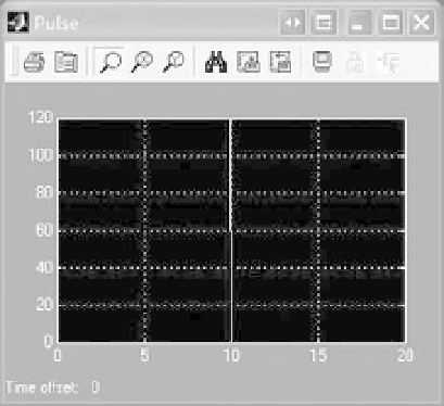
The final step is to open the “Simulation Parameters” to change the simulation “Stop time” to
20 and click the run button. The preceding figure displays the output of the three scopes.
In some simulations, a model's performance is evaluated by changing parameter values. For
the model in this example, the block parameters would need to be changed individually. For a
model with hundreds of parameters, this would entail a considerable effort. It is far easier to enter
the parameter values in MATLAB and use the parameter names in the blocks rather than values.
For instance, enter the following in MATLAB
>>
PulseGain
¼
120;
>>
PulseDuration
¼
10;
>>
Gain
¼
10;
>>
Gain1
¼
60;
>>
Gain2
¼
5;
>>
Gain3
¼
5;
>>
Gain4
¼
40;
>>
Gain5
¼
5;
>>
Gain6
¼
1/3;
>>
1/4;
Then in each gain block, use the parameter name rather than the value. Any changes in the
MATLAB values are automatically updated in SIMULINK. Defining initial conditions for integrator
blocks can also be done in MATLAB. To avoid entering the parameter values each time MATLAB is
opened, store the values in an m-file.
Gain7
¼
It is often convenient to use subsystems to collect blocks together when drawing a
SIMULINK model to make a model more readable. In the previous example, for
instance, the pulse input is easily drawn as a subsystem by selecting the blocks by col-
lecting them in a bounding box with the mouse pointer (i.e., use the mouse to draw a
box around the elements), right-clicking the mouse and then selecting “Create subsys-
tem”.Theinputsandtheoutputstothesubsystemarethoseoftheelementsinthe
selected blocks. Shown in Figure A.13 is part of the model from the previous example