Biomedical Engineering Reference
In-Depth Information
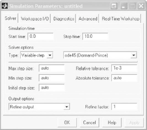
FIGURE A.12
Simulation Parameters window.
variable-step size simulation often saves simulation calculation time, resulting in a faster
simulation. To run the simulation, select the command “Start” from the “Simulation” menu
or the run command icon.
After creating a SIMULINK model, use “Save” or “Save As” from the “File” menu to
save the model. Many simulation models have a number of parameters, some of which
are changed from simulation to simulation. For convenience, it makes sense to define the
parameters in MATLAB (i.e., K
3, etc.), with the parameter values saved in an m-file.
The m-file can then be opened in MATLAB and these parameters can then be used in the
SIMULINK model. To print the SIMULINK model, select the “Print” command from the
“File” menu, or select the “Copy Model to Clipboard” command from the “Edit” menu
and paste it into another application like Microsoft Word.
¼
5, M
¼
EXAMPLE PROBLEM A.8
Simulate the response of the system described in Example A.7 with zero initial conditions if the
input
f
(
t
) is a pulse with magnitude 120 and duration 10 applied at
t
¼
0.
Solution
Whenever we create a SIMULINK simulation, it is best to begin by drawing the block diagram
for the system. In Example A.7, we already created the block diagram where the highest deriva-
tive was first solved in each equation and all of the other terms were placed on the right-hand side