Biomedical Engineering Reference
In-Depth Information
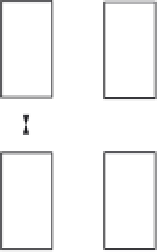
N
S
S
N
Attractive
Force
Repulsive
Force
N
N
S
S
(a) (b)
FIGURE 16.31
Attractive (a) and repulsive (b) magnetic forces for two arrangements of permanent magnets
with north (N) and south (S) poles.
M
0
B
0
FIGURE 16.32
Alignment of magnetic dipoles in a static magnetic field
B
0
and the net magnetization.
opposing the field (antiparallel), as shown in Figure 16.32. Most of them will line up along
the applied field because less energy is required to maintain that orientation. The overall
vector summation of the individual dipole moments results in an overall net magnetization
M
X
^
¼
u
n
ð
16
:
54
Þ
0
n
as shown in the figure.
The energy required for the transition from one spin state to another is governed by
D
E
¼
hv
ð
16
:
55
Þ
10
34
in which Plank's constant is
h
¼
6.626
J
-
s
. The physical meaning of this relation is
that a photon of frequency
is either absorbed to send an electron to a higher energy state
or it is radiated for the electron to fall to a lower state. Eventually, excited electrons return
to their original equilibrium state. Unlike x-ray imaging that emits ionizing radiation, only
harmless photons are emitted during this mechanism that is used in MRI.
What is the frequency necessary for this transition? Returning to the last case of a charge
revolving about the nucleus in a static magnetic field, the spin gyromagnetic ratio,
v
g
, from
quantum mechanics for a spinning electron is
q
/
m
. The orientation of the spin results in a
left-hand rule (clockwise about
B
0
). Like Eq. (16.53b), substitution for frequency equation
yields
v
L
¼
2
p
¼
2
0
p
B
¼ g
B
ð
16
:
56
Þ
0
0