Biomedical Engineering Reference
In-Depth Information
16.2.6 Diffraction
Waves transmitted by a transducer are not plain but form a complicated pattern. The for-
mation of these patterns, as shown in Figure 16.20, is caused by the radiation of sound
waves from different locations on the aperture (transducer face) and the mutual interfer-
ence of these radiated waves. This phenomenon, also called diffraction, is a consequence
of the aperture dimensions that are on the order of wavelengths.
The two most common aperture shapes are the circle and rectangle, as shown in
Figure 16.21. A slice of the three-dimensional beam in a plane is what is usually depicted in
graphs. For the circle, because of symmetry, any plane through the beam axis (here the
-axis)
will be identical. For the rectangular aperture, the beam formation differs in all planes through
the beam axis, and the most important planes for imaging are the
z
and
-
planes. The beam
x-z
y
z
amplitude described by Figure 16.20 corresponds to an
plane from a rectangular aperture.
Beams have recognizable landmarks. A method borrowed from maps is a contour plot of
the acoustic pressure magnitude, often depicted in dB relative to maximum amplitude at
each depth. Of particular interest is the -6 dB contour. A cross section of the beam, perpen-
dicular to the beam axis, is called a beam plot. The width between points of this -6 dB
-
x
z
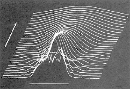
FIGURE 16.20
-axis. The vertical axis inten-
sity and beam profiles are shown at intervals of about 70 wavelengths along the beam axis that is compressed rela-
tive to the lateral dimension (1,920 wavelengths are shown along the
Diffracted field of a 40-wavelength-wide line aperture along the
x
z
-axis).
y
a
L
y
x
L
x
z
z
FIGURE 16.21
(Left) Circular aperture of radius
a.
(Right) Rectangular aperture with lengths of
L
x
parallel to
the
x
-axis and
L
y
parallel to the
y
-axis. The
z
-axis is perpendicular to the
x
-
y
plane of the aperture.