Biomedical Engineering Reference
In-Depth Information
From the transducer electrical equivalent circuit in Figure 16.9a,
Z
A
is radiation imped-
ance of which
R
A
and
Z
A
are its real and imaginary parts.
R
A
(
)canbefoundfromthe
f
totalrealelectricalpower,
W
E
, flowing into the transducer for an applied voltage
,
V
and current
I
2
W
E
¼
II
*
R
A
=
2
¼j
I
j
R
A
=
2
ð
16
:
26a
Þ
R
A
(f)
Z
T
(f)
iX
A
(f)
−
iX
0
=
−
i/
w
C
0
(a)
3000
2000
1000
Real(Z
T
)
iX
A
0
1000
iX
0
−
Imag(Z
T
)=X
A
−
X
0
2000
3000
0
0.5
1
1.5
2
2.5
3
3.5
4
4.5
5
Frequency (MHz)
(b)
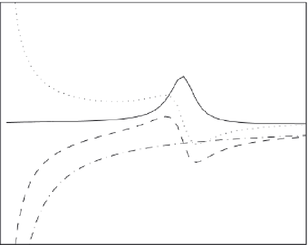
FIGURE 16.9
(a) Transducer equivalent circuit and (b) transducer impedance as a function of frequency.