Biomedical Engineering Reference
In-Depth Information
500
µ
m
(a)
Base
Indicator
Cycle 3
Cycle 2
Cycle 1
Re
12
Re
70
Cycle 1
Cycle 2
Cycle 3
(b)
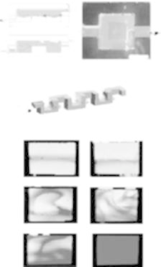
FIGURE 11.33
Microfl uidic components. (a) A passive check valve in a multilayer structure of poly-
dimethylsiloxane (PDMS). The upper schematic shows the valve in the closed position: pressure applied
from the right presses the fl exible diaphragm against a post, blocking fl ow through the hole in the center
of the diaphragm. The lower schematic shows the valve in the open position: pressure applied from the left
lifts the diaphragm off the post and allows fl ow through the diaphragm hole. The image on the right shows
fl ow of a fl uorescent fl uid through the valve. (b) The design of this chaotic advection mixer exploits the
character of laminar fl ow in a three-dimensional serpentine channel to mix adjacent streams in a single fl ow.
A solution of pH indicator runs adjacent to a stream of basic solution and reveals the progress of mixing.
As the two solutions mix, the indicator becomes red. Mixing is effi cient even at low Reynolds numbers.
Although the fl ow is laminar, there are weak eddies in the corners [163, 167]. Source: http://www.niherst.
gov.tt/scipop/sci-bits/microfl uidics.htm (see Plate 13 for color version).


Search WWH ::

Custom Search