Biomedical Engineering Reference
In-Depth Information
The mask used in photolithography is typically a glass substrate with many segments
of blocked and unblocked regions. UV light which passes through the unblocked seg-
ments of the mask will activate the protective photolabile group (MeNPOC) and result
in different solubility between the blocked and unblocked regions. Different masks can
be designed to make any types of array of oligonucleotide probes for a wide variety of
applications.
Work by Lipshutz [11] has shown that for an m-mer probe, a maximum of 4
m
cycles
is required to generate a complete set of probe sequence of
m
length. That is to say, for
a probe with 15-mer, a total of 60 cycles is needed to generate the complete array of a
15-mer probe. Using the lithography mask, four regions with four different DNA bases
(A, C, G, and T) are created on the substrate. Using the same mask again (but placed
perpendicularly to the previous steps this time) will result in a probe length of 2-mer.
For a 3-mer probe (trinucleotides), another mask that is one quarter the width of the
previous mask is used and so on.
11.2.2.3 Fabrication by inkjet/piezoelectric methods (indirect-deposition
approach)
DNA array fabrication by inkjet method has a very similar working principle to that
of an inkjet printer which sprays ink onto paper that is to be printed. Inkjet printing is
a non-contact printing technology where oligonucleotide probes are sprayed onto the
array surface without touching it; thus reducing the risk of cross-contaminations. This
is different from the robotic microprinting and photolithography methods which apply
the probes directly onto the substrate.
In his work, Wallace [12] formed inkjet printheads from the rectangular blocks
made of piezoelectric material. A diamond saw is used to create fl uid channel grooves
and channel actuator structures. These grooves are approximately 1
µ
m apart, 360
µ
m
deep and 170
m wide. Next, a cover plate is attached to the top of the grooves to form
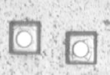
an enclosed rectangle channel for the working fl uids. A polymer orifi ce plate (see
Fig. 11.3) with many 40
µ
µ
m diameter orifi ces is attached to the other end of the grooves.
FIGURE 11.3
Orifi ce plate with 40 µm diameter orifi ces.


Search WWH ::

Custom Search