Biomedical Engineering Reference
In-Depth Information
C
i
Gate insulator
C
sc
Si
(a)
DNA
Ions
C
ML
R
ML
C
i
Gate insulator
Si
C
sc
(b)
FIGURE 7.3
Simplifi ed equivalent circuit of an original (unmodifi ed) EIS structure (a) and EIS biosen-
sor functionalized with charged macromolecules (b).
C
i
,
C
sc
and
C
ML
are capacitances of the gate insulator,
the space-charge region in the semiconductor, and the molecular layer, respectively;
R
ML
is the resistance of
the molecular layer.
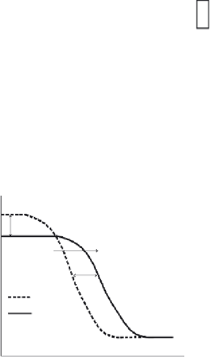
∆
C
Increasing of negative
charges on an insulator
surface
∆
V
fb
EIS
EISDNA
p-Si
Voltage
FIGURE 7.4
Capacitance-voltage (
C-V
) curve for a bare (unmodifi ed) EIS sensor and EIS sensor with
a molecular layer (here, DNA). The presence of the additional molecular layer shifts the
C-V
curve of the
original EIS structure along both the capacitance (∆
C
) and voltage axis (∆
V
fb
).


Search WWH ::

Custom Search