Biomedical Engineering Reference
In-Depth Information
barrier oxide
B
A
A
2
A
1
1 μm
open pore bottoms
C
10
8
R
el
10
7
R
ox
C
ox
10
6
10
5
10
4
10
-2
10
-1
10
0
10
1
10
2
10
3
10
4
10
5
10
6
f
/ Hz
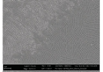
Figure 6. A) Scanning electron microscopy image of the porous alumina substrate
after partial opening of the pores, and B) schematic drawing of the substrate. C)
Impedance spectra of a porous alumina layer (Ŷ) before and (Ƒ) after pore bottom
opening. The solid lines are the results of the fitting procedures. For (Ŷ), the
equivalent circuit shown in the inset was used with the following results:
R
ox
= 0.3
Gȍ,
C
ox
= 2.6 nF and
R
el
= 5400 ȍ. For (Ƒ), an equivalent circuit comprising the
electrolyte resistance
R
el
in series to a CPE-element, representing the non-ideal ca-
pacitive properties of the platinised platinum electrodes, was used with the follow-
ing results:
R
el
= 4300 ȍ, A = 0.6 mF s
Į
-1
and
Į
= 0.80. Inset: Equivalent circuit
composed of a parallel connection of a resistance
R
ox
and a capacitance
C
ox
repre-
senting the aluminium oxide in series to the electrolyte resistance
R
el
.
38
As only the porous area fraction of the substrate (
p
= 33 ± 3
%) is considered electrically active,
25
these areas translate into
A
1
= 0.0026 cm
2
and
A
2
= 0.0078 cm
2
, respectively. However, alumi-
na is not an ideal insulator, as shown by EIS. The mean specific
capacitive values
C
ox,sp
of the remaining barrier oxide is (1.1 ± 0.3)
μF cm
-2
(
n
= 16), the specific resistance
R
ox,sp
varies from 10
4
-10
7


Search WWH ::

Custom Search