Biomedical Engineering Reference
In-Depth Information
TABLE 9.4
Dimension Range of Samples
Span (mm)
Width (mm)
Height (mm)
85
4.0 ± 1.0
19 ± 3.0
Computer
with A/D converter
BioAmplifier
Instron control tower
Head stage
P
i
´
i
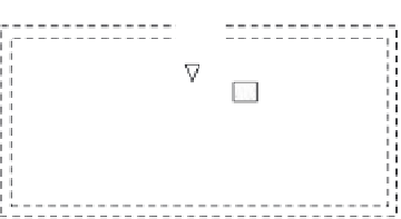
FIGURE 9.15
Setup of the test system for three-point bending test.
shown in Table 9.4. Conductive silver adhesive (5001, SPI, United States) was
painted on both sides of the specimens as electrodes with dimensions of
3 mm × 3 mm. Two types of specimen were used with different electrode
distributions. Figure 9.14(b) shows type A with six pairs of electrodes and
Figure 9.14(c) shows type B with two pairs of electrodes. Two electrodes on
both lateral sides of a sample comprised a pair of electrodes located at the
same height of both lateral sides, as shown in Figure 9.14.
The electrodes attached to the type A sample are denoted by the numbers
1 to 6 on one side and 1′ to 6′ for the corresponding electrodes on the other
side, facing the medullary cavity. Then, 1-1′ to 6-6′ represent the six pairs of
electrodes, respectively; similarly, 7-7′ to 8-8′ represent the two pairs of elec-
trodes on the type B sample. When the samples were subjected to four-point
bending, all six pairs of electrodes on the type A samples experienced pure
bending deformation, whereas on the type B samples only electrodes 8-8′
experienced pure bending deformation.
The experimental setup of the measurement system used in Fu et al. [23]
is similar to that shown in Figure 9.10, except that a pair of electrodes
i
-
i
′
was used, as shown in Figure 9.15. Taking as reference an electrode on the