Biomedical Engineering Reference
In-Depth Information
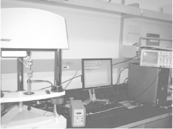
PVDF Film
Load Cell
Charge Amplifier
Figure 3.6
The experimental setup used for measurement of piezoelectric coefficients
d
31
and
d
32
3.4.1.1 Measurement of
d
31
and
d
32
Since there is no electrical (charge) output for piezoelectric materials in response to
applied DC loads, the conventional method of measuring piezoelectric coefficients is to
apply periodic loads. A sinusoidal force is the simplest waveform for this purpose and
the frequency of this load should, preferably, be higher than its cut-off frequency.
2
The
experimental setup is illustrated in Figure 3.6.
In order to measure
d
31
, samples of the piezoelectric coefficient of (Goodfellow) PVDF
film were incised in such a way that the drawn direction of the film was parallel to their
length. Alternatively, in order to measure
d
32
, samples were cut from the film in such a
way that their drawn directions were perpendicular to the length of the samples.
The effective length and width of the 110 μm thick sample were, respectively, 20 and
8 mm. In order to calculate coefficients
d
31
and
d
32
, as shown in Figure 3.7, both the
stress and charge density were required. The tensile stress was calculated from the applied
force and cross-sectional area of the film. By knowing the amount of charge and also the
surface area of the film (metalized area), charge density was calculated. The coefficient
d
31
is the ratio of charge density to the tensile stress.
These measurements conformed favorably with the nominal values quoted by Goodfel-
low [19], with
d
31
= 19.0
±
0.3 pC N
−
1
and
d
32
=2.0
±
0.1 pC N
−
1
. (The values quoted
by Goodfellow were 18
−
20 pC N
−
1
and 2 pC N
−
1
for
d
31
and
d
32
, respectively.)
2
Piezoelectric PVDF can simply be modeled as a voltage source in series with a capacitor (C). Alternatively, the
input impedance of an amplifier can be modeled as being a resistor (R) in which the combination of both R and
C acts as a high-pass filter. At a specific frequency (the cut-off frequency), this resistance R and capacitance C
causes an attenuation of 0.707 compared to the input amplitude so, in order to avoid this, the normal working
frequency must always be greater.