Biomedical Engineering Reference
In-Depth Information
8.3.2.2 Graphical Representation of Localized Lumps in Two Dimensions
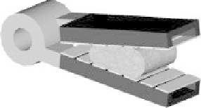
Figure 8.17 illustrates the second prototype grasper in which both upper and lower jaws
are equipped with arrays of sensors. Using this grasper, it is possible to locate lumps in
two directions, along the jaw (
x
-axis) as well as its depth (
y
-axis).
The steps used for the construction of 2D tactile images are demonstrated in Figure 8.18.
For better clarification of the algorithm used in this study, consider the case illustrated
in Figure 8.19a. This figure demonstrates a grasped tissue which contains a lump that
is aligned with sensing elements 2
U
and 2
L
, where the subscripts U and L refer to the
upper and lower sensing arrays, respectively. The distance of the lump from the upper
and lower sensing elements are shown by '
a
'and'
b
', respectively.
Figure 8.19b shows the 2D intensity graph which was built using a one-dimensional
algorithm, as explained in Section 8.3.2.1. This graph consists of two rows of color bands,
which correspond to two arrays of sensors, one on the top and the other at the bottom.
Therefore, this graph can be considered as a matrix with two rows (color bands) and
seven columns (sensors), that is, 2
7 cells. The corresponding matrix in which each
element represents voltage amplitude is in the following form:
×
V
U
1
V
U
2
V
U
3
V
U
4
V
U
5
V
U
6
V
U
7
[
V
]
=
(8.11)
V
L
1
V
L
2
V
L
3
V
L
4
V
L
5
V
L
6
V
L
7
As can be seen, Figure 8.19b is unable to show the precise location of the lump so, in
order to provide this valuable information, the dimensions of the matrix (and consequently
the number of matrix elements) were increased. The graphical enhancement in the
x
-direction was explained in the previous section; hence in this section the row operations
(
y
-direction) are emphasized.
As shown in Figure 8.18, the number of rows was increased to
M
by inserting (
M
−
2)
rows of zeros between the first and second rows of the matrix which led to an
M
×
7
matrix. Furthermore, using the technique explained in Section 8.3.2.1, the number of
columns was also increased to
N
. The resulting
M
×
N
matrix would be in the form:
⎡
⎣
⎤
⎦
G
U
1
G
U
2
···
G
U
N
−
1
G
U
N
00
···
0
0
G
0
=
.
.
.
.
.
.
.
(8.12)
00
···
0
0
G
L
1
G
L
2
···
G
L
N
−
1
G
L
N
Embedded lump
y
x
Figure 8.17
The second design of grasper in which both upper and lower jaws are equipped with
the sensing elements