Biomedical Engineering Reference
In-Depth Information
1
2
2
1
2
3
4
4
(b)
(a)
Hard Object
F
2
F
1
F
2
F
2
F
1
F
2
(c)
(d)
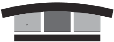
Figure 8.2
(a) Cross-sectional view of the sensing element: (1) rigid cylinder, (2) compliant cylinder,
(3) PVDF, and (4) substrate. (b) Isometric view of the sensing element. (c,d) Transfer of load from
rigid to compliant cylinder for a soft object and hard object, respectively [1]
is the thickness of the rigid and compliant cylinders (which are the same),
E
1
is the
Young's modulus of the sensed object, and
E
2
is the modulus of the compliant cylinder.
The larger the value of the force ratio, the stiffer the sensed object is when compared to
the compliant cylinder.
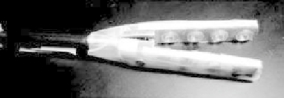
The integration of eight tactile sensor units with the prototype grasper is shown in
Figure 8.3.
Each sensing element in the grasper has two output signals, one from the PVDF under
the rigid cylinder and the other from the PVDF under the compliant cylinder. Two arrays
of four sensors are microfabricated on the grasper, one on the upper jaw and the other on
the lower jaw. These two arrays, numbered from
U
1
to
U
4
on the upper jaw and
L
1
to
L
4
on the lower jaw, are shown in Figure 8.3a,b.
(a)
Upper jaw
Sensing elements
Lower jaw
(b)
Figure 8.3
(a) Photograph of a grasper. (b) The two arrays of sensing elements