Biomedical Engineering Reference
In-Depth Information
Graphical
display
Rendering
algorithm
Signal
processing
Smart MIS
grasper
DAQ
Tissue
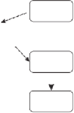
Figure 8.1
The schematic diagram of the complete system
shown schematically in Figure 8.1. When the surgeon uses the endoscopic grasper to
grasp a tissue, the sensor array measures the softness of the grasped tissue under each
sensing element. The electrical outputs of the piezoelectric sensing elements are then
conditioned and transmitted to the DAQ system (NI PCI-6225), with which signals are
amplified, filtered, digitized, and processed by a computer. A computer code was devel-
oped in the LabVIEW environment for signal conditioning such as filtering-out line noise.
A representation algorithm, as later elaborated in this chapter, was used to map the fea-
tures of the extracted signal to a grayscale image. Using the constructed images, the
surgeon is able to establish the softness of the grasped object.
8.2.1 Feedback System
The smart endoscopic grasper consists of an array of tactile sensors, a charge amplifier, and
a DAQ card. Each sensor in the tactile sensor array produces two analog voltage outputs
as a result of the force applied by the grasper to the object. These voltages relate to the
softness of the grasped object and interface with a DAQ card via the charge amplifiers and
buffers. The connection of the sensors to the DAQ card needs extra electronic components
of which further explanation is given in the following sections.
8.2.2 Sensor
The sensor unit consists of a rigid cylinder surrounded by a compliant cylinder. As shown
in Figure 8.2a, a polyvinylidene fluoride (PVDF) sensing element (Goodfellow Company,
USA) is positioned under both the rigid and compliant cylinders upon both of which a
load is applied when an object is in contact with the sensors.
As depicted in Figure 8.2c,d, the softer the contact object is, the more of the load
will transfer from the rigid cylinder to the compliant cylinder [2, 3]. The load ratio in
Figure 8.2 can be calculated as follows [1, 2]:
F
1
F
2
=
1
+
T
2
E
1
(8.1)
T
1
E
2
where
F
1
is the force sensed by the PVDF under the rigid cylinder,
F
2
is the force sensed
by the PVDF under the compliant cylinder,
T
1
is the thickness of the sensed object,
T
2