Biomedical Engineering Reference
In-Depth Information
The elastomeric material that was primarily used in the compression tests was also used
in the experimental work as soft tissue. Two acrylic balls of different sizes (3 and 4 mm),
simulating the lumps, were inserted into the hollow spaces that were carefully carved out
of the bulk elastomeric. To change the depth of the lumps, several layers of the elas-
tomeric material were cut into the same dimensions but different thicknesses. The lumps
were placed in one of the layers so that other elastomeric layers could be used as spacers
to increase or decrease the distance of the lump layer from the top or bottom surfaces,
while the total thickness was kept constant. A dynamic load was applied by a shaker,
which was driven by a power amplifier and a signal generator. To register the pressure
distribution on the contact surface, an array of 1.5 mm wide, 28 μm thick PVDF films
were positioned 0.5 mm apart. A picture of a sensor with seven sensing elements is shown
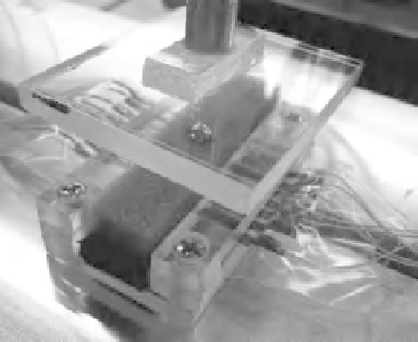
in Figure 6.10. To apply uniform distributed load, a flat plate was attached to the probe,
as shown in Figure 6.11. The experimental setup has been explained in previous chapters
and is shown in Figure 3.23. The outputs of the sensors were fed into the connector box
through an interface circuit.
The data was then transferred to the computer using a DAQ (NI PCI-6225, National
Instruments). To reduce the noise effect in each experiment, the average of the peak values
Interface Circuit
PVDF
Sensing Elements
Figure 6.10
A sensor with seven sensing elements is connected to the DAQ (See Plate 13)
Compression
Plate
Probe
Lump
Soft Object
Sensor Array
PVDF
Sensing
Elements
Figure 6.11
Soft object with embedded lumps under test. The top plate was used to replicate the
upper jaw of the grasper in order to apply compressive loads