Biomedical Engineering Reference
In-Depth Information
silicon
PVDF films
attached to
beams
PVDF films
at Supports
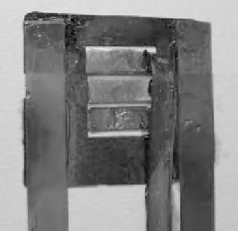
Figure 4.33
The top part of the sensor. PVDF films at the supports as well as films attached to
the beams are shown. The direction of the PVDF films are also illustrated (See Plate 8)
from which two pieces of 22
×
4 mm film were cut in such a way that the drawn direction
of each film was parallel to the film length. (Refer to Figure 4.17 in which arrows show the
drawn direction.) This was done to minimize the output of the PVDF films at the supports
due to any unwanted load and maximize the sensitivity of the output to the compressive
load only. These two films were glued to the top of the supports. Of its total 22 mm
length, 18 mm was used as the active area, and the remaining 4 mm used to connect the
electrodes. Electrodes were cut from a thin copper foil and adhered to the PVDF films
using conductive glue. For the suspended beams, three 2
×
12 mm PVDF films were
used, in which each was cut in such a way that the drawn direction was in line with the
PVDF film length. A picture from the backside of the top part is shown in Figure 4.33.
After connecting electrodes to the films, they were glued to the top silicon part.
The wiring of these three films was passed through the empty space between the top
and bottom parts. Finally, there were five pairs of wires, of which each pair belonged to
one sensing element. The top part, upon which all the PVDF films were adhered, was
glued to the bottom silicon part and then, for subsequent testing, the assembled sensor
system was placed on a Plexiglas block. The hybrid assembled MEMS sensor is shown
in Figure 4.34.
4.2.5 Testing and Validation: Softness Characterization
In order to validate the simulation results, a softness sensing experiment was conducted
utilizing the microfabricated sensor. Prior to conducting the softness tests, it was required