Biomedical Engineering Reference
In-Depth Information
0.0
Theoretical
FEM
−0.2
−
0.4
−0.6
−
0.8
−
1.0
0.0
0.5
1.0
Beam length (normalized)
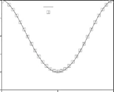
Figure 4.21
The deflection curve of the first beam when a distributed load of 111 kPa is applied
to the beam and its two end supports. Solid line illustrates the result obtained from Equation 4.4,
while the squares indicate the FEM results
This figure also illustrates the result of theoretical analysis for a clamped - clamped
beam under a distributed load, which was obtained from the known formula:
Wx
2
1
24
EIL
2
Lx
−
L
2
−
x
2
y
=
(4.4)
in which,
L
: Beam length (m)
W
: Total applied load (N)
E
: Young's modulus of the beam (N/m
2
)
I
: Area moment of inertia (m
4
)
x
: Distance of point on the beam from the origin, here the left support (m).
It is worth noting that the cross section of the beams after microfabrication using
anisotropic wet etching was trapezoidal. In order to compare the experimental results
with those of the closed form and FEM, the equivalent rectangular cross section was
modeled. It was found that the moment of inertia of a rectangular cross section with a
width of 2.12 mm and a thickness of 180
m is equal to the moment of inertia of the
etched cross section. This is shown in Figure 4.22.
This equivalent moment of inertia and cross section were used in the closed form
relationship and finite element model. For a distributed load of 111 kPa, the output voltage
of PVDF films associated with the first beam was calculated. The output voltage of the
middle PVDF film attached to the beam was 680 mV. The calculated voltage for two
supports was 85 mV. The equality of voltages of the two supports confirms that the applied
load was uniform. For this loading condition, no output voltage from the middle PVDF
μ