Biomedical Engineering Reference
In-Depth Information
(a)
physical movement
(b)
virtual motion
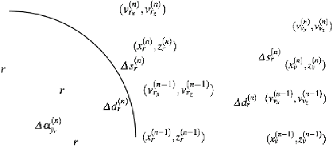
Fig. 10.3
Illustration of two-dimensional mappings in the
xz
-plane from (
a
) tracking coordinates
to (
b
) virtual coordinates for an applied curvature gain
g
C
/
r
with radius
r
∈ R
+
=
1
virtual
camera
coordinates
(b)
virtual motion
(a)
physical movement
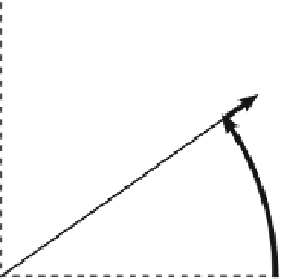
Fig. 10.4
Illustration of (
a
) path redirection with curvature gains in the physical workspace, for
(
b
) a predicted virtual straight path
v
(
n
)
v
(
n
)
v
(
n
)
v
(
n
)
2
with
(
,
)
∈ R
(
,
)
=
in Fig.
10.3
a, as well as
1 in the virtual
workspace shown in Fig.
10.3
b. Other implementations may use arbitrarily placed
curvatures in the physical workspace, e.g., based on real and virtual path planning and
transformations [
20
,
26
,
34
]. Figure
10.4
shows an example of a predicted straight
motion in the VE being mapped to a circular path in the physical workspace.
It is important to note that curvature transformations are based on the assumption
that the user will adapt to induced virtual rotations by changing the walking direction
in the physical workspace. In particular, if the manipulations are overt, the user has
to consciously follow the induced virtual rotations. If the user does not adapt to an
induced rotation in the virtual environment, e.g., if the user is walking with eyes
v
x
v
z
v
x
v
z