Biomedical Engineering Reference
In-Depth Information
r
(
n
)
p
(0,0,0)
lab
y
lab
y
virtual
reference
coordinates
virtual
scene
coordinates
virtual
camera
coordinates
lab
z
lab
z
(b)
virtual workspace
(a)
physical workspace
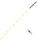
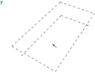
Fig. 10.1
Illustration of (
a
) three-dimensional tracking coordinates in a VR laboratory with a user's
tracked local head coordinate system as defined by positional and orientational tracking data, and
(
b
) virtual scene coordinates with interaction volume defined by reference coordinates
mations.
2
Although the axes and order of yaw, pitch and roll transformations are not
standardized among tracking systems, practitioners tend to represent orientations
first with yaw rotations around the
y
-axis, followed by pitch rotations around the
x
-axis, and roll rotations around the
z
-axis [
35
]. For instance, assuming the user's
head position and orientation is tracked with a local coordinate system that is defined
with the
z
-axis for the (inverse)
look
-direction, the
y
-axis in
up
-direction, and the
x
-axis in
strafe
-direction (see Fig.
10.1
a), then yaw, pitch and roll rotations corre-
spond to turning the head to the left or right, up or down, or around the view axis,
respectively. In the following, we assume tracked head orientations to be provided
using this representation.
In order to provide a user with visual feedback by rendering the three-dimensional
scene onto one or more VR display surfaces, we have to consider a virtual analog of
the user's head in the VE.
3
We assume virtual camera coordinates are represented
with the triple of orthogonal axes as used for physical head tracking coordinates [
8
],
with transformations from the origin of the virtual scene to the camera coordinates
defined by a translation vector
3
, and yaw, pitch and roll angles
(
x
v
,
y
v
,
z
v
)
∈ R
3
. Figure
10.1
b illustrates local camera coordinates in virtual
(
˜
y
v
,
˜
p
v
,
˜
r
v
)
∈[
0
,
360
)
scene coordinates.
2
Some tracking systems use quaternions as their native reporting format, which provides an alter-
native representation of the transformations, and can be converted from and to the angular notation
used in this chapter [
21
].
3
Depending on the display system (e.g., head-mounted displays or immersive projection tech-
nologies) the actual positions or orientations of computer graphics camera objects are usually
specified relative to these head coordinates, such as transformations from the head center to the eye
displays [
25
].