Biomedical Engineering Reference
In-Depth Information
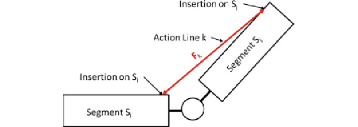
Fig. 8.4
Action line joining two adjacent segments S
i
and S
j
. The insertions of this action line in
both segments are given by anthropometric tables in each local reference frame
between the maximum delivered force and the length of a muscle (named Force-
Length relation). This relation is given in the biomechanical literature. Hence a
muscle tension F
i
for muscle i is constrained by:
0
≤
F
i
≤
K
(
l
)
×
K
0
×
PCSA
l is then the distance between the two insertion points of the action line. Motion
capture data enable to associate a local reference frame to each body segment, as
shown previously for the computation of joint angles. It is thus possible to apply
anthropometric tables that give the local coordinates of each line action insertion
in each bone. These tables are generally embedded in dedicated software, such as
OpenSim (see
http://simtk.org/home/opensim
for an example).
Knowing these insertion points for each action line, we can deduce the length of
each action line and consequently its MVC in the current pose. If external torques
τ
ext
are also known, such as gravity and the momentum of all the contact forces, the
torques applied by the muscles
τ
musc
in static condition are given by:
τ
ext
=−
τ
musc
In the remaining of this section we assume that the system is static for simplifica-
tion but extension to dynamic situation simply involves adding to this formulae the
terms linked to the derivative of the angular momentum of each body segment.
τ
ext
could be expressed for each body segment i as:
m
M
j
i
i
ext
∀
i
∈
[1
,
n
]
,
=−
τ
j
=
1
where n is the number of body segments, m is the number of independent action
lines, and M
i
stands for the moment of action line j on the ith body segment. If the
local reference frame O
i
of segment i is placed on the proximal joint: