Biomedical Engineering Reference
In-Depth Information
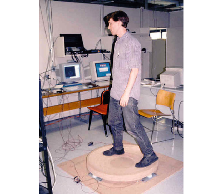
Fig. 7.15
Virtual Motion Controller. Courtesy of Thomas Furness, Human Interface Technology
Laboratory, University of Washington
motion they sense. The type of diagram that they use is shown in Fig.
7.17
.Itclassifies
a single device as a union (indicated by connecting dashed lines) of individual sensors
(the circles connected with solid lines). We can see that the device might sense
linear absolute position (P), linear relative position (dP), linear absolute force (F),
linear relative force (dF), rotary absolute position (R), rotary relative position (dR),
rotary absolute force (T for tensor), or rotary relative force (dT). We also see how
many degrees of freedom each device senses (X, Y, Z for linear degrees of freedom,
and rX, rY, rZ for rotary degrees of freedom), and the resolution: from continuous
(Inf) through to discrete (1). Thus a common mouse is a combination of a two-
dimensional relative position (X, Y) sensor with continuous movement plus typically
2 discrete buttons (Z, but only two position values, indicating 0 or 1) plus a scroll
wheel reporting a number of discrete positions of the wheel as relative rotation. The
diagram thus depicts the mouse as three separate units (position, buttons, scroll wheel)
connected by dotted lines. The two dimensions of the mouse are joined together by
a solid line because they are reported by the same sensor in the mouse.