Biomedical Engineering Reference
In-Depth Information
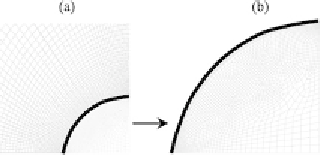
Figure 4.
Presentation of the unstructured mesh grid that is used for the integration of the model.
(a) Mesh grid in the neighborhood of the droplet. (b) Shows a magnification of the mesh used to
describe the droplet. Black line is the water/air interface.
step consists in the resolution of Eq. (8) that gives the temperature everywhere in
the vapor phase and therefore also nearby the water/air interface. The computed
temperature at the interface is then used as a boundary condition input for Eq. (7)
that is then integrated together with Eqs (6), (7) and (10). From this second step,
the function
φ(θ)
is obtained. In the last step, the time evolution of the droplet mass
is computed from Eq. (9) with a basic leap-frog scheme. As droplets are assumed
to have a spherical cap geometry, the mass loss corresponds to a decrease of
θ
that
can be readily computed from the droplet's mass and that is finally used to evaluate
the new location of the water/air interface for the next time step round.
Hydrodynamic simulations are based on the discretization of space by a mesh
grid that has to be adapted to the problem under investigation. For the simulation
of water/air interfacial properties, a special care has to be devoted to the mesh grid
structure nearby this interface and at both the droplet apex and contact line. Sin-
gularities in the hydrodynamics show up in these two locations and unstructured
meshes have to be used to properly catch all the features occurring in these interfa-
cial regions. Figure 4 illustrates the mesh structure that will be used in the following
as well as its refinement in the neighborhood of the interfaces. Inside the droplet and
in the far field a coarse meshing is imposed and will be sufficient for our purpose.
Figure 4 displays only part of the simulation domain and in all the runs, far field
boundary is actually rejected at a distance of 160
R
that was shown to be large
enough for the finite size of the simulation domain to become negligible. As sub-
strate is assumed to be ideal here, there is no need to describe it explicitly since its
influence appears only through the water/substrate boundary conditions described
by
T
s
and
L
s
[48]. Several works avoid ideal substrate approximations and deal with
substrates with finite heat conductivity. It was shown that temperature gradients can
occur at the liquid/substrate interface as well as inside the substrates and that they
can contribute to changes in the hydrodynamics of the droplets [34].
As evaporation proceeds, the droplet volume decreases and a remeshing is used
for each time step to keep track of the water/air interface. This procedure is tedious
and CPU time consuming but it ensures the accurate description of the interface
location as well as properties especially for the implementation of Eq. (10). As this
latter only comes into play at the level of the water/air interface, is it discretized
only with the mesh cells located at this boundary (see black line in Fig. 4).
Search WWH ::

Custom Search