Biomedical Engineering Reference
In-Depth Information
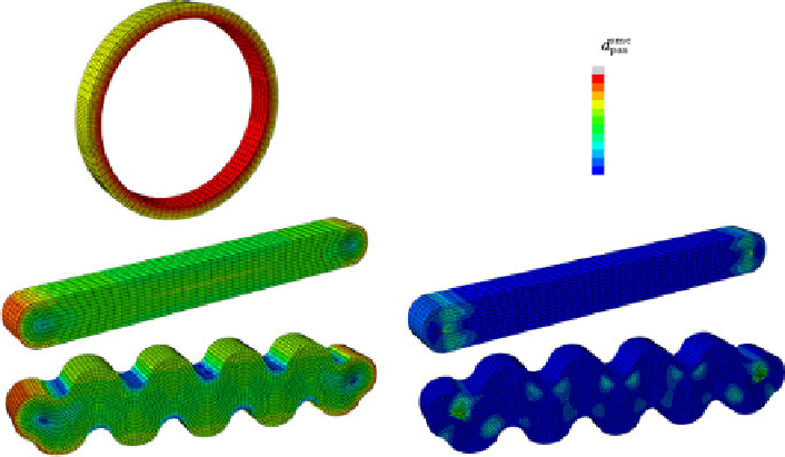
Fig. 10.4
Maximum principal stress in an arterial segment at systolic pressure (
top left
), when
clamped up to a clamping force of 5 mN with a smooth clamp (
middle left
) and when clamped up
to 5 mN with a mosquito clamp (
bottom left
). Damage variable
d
smc
pas
in the same segment, for the
smooth clamp design (
top right
) and for the wavy clamp design (
bottom right
)
accumulation of clamping is present, but no further damage is induced. Similar to
step 1 of Sect.
10.5.1
, the segment is closed to form a half cylinder in step 5, thus
incorporating the circumferential residual stress. To reproduce the experimental sit-
uation, this time, no longitudinal stretch or internal pressure was added. Next, in
step 6, a rod is translated radially from inside the section, pulling it until it exerts
a certain load, corresponding to the experimentally measured value after complete
relaxation due to the addition of SNP. A friction coefficient of
μ
rod
0
.
3isused
between the rod and the outer arterial surface. Up to the end of step 6, no smooth
muscle cell contribution is added in the material model. This is accomplished by
multiplying the fractions
n
III
and
n
IV
with a switch function that is set to zero in
steps 5 and 6.
After reaching the relaxed state, in the final step, the switch function is smoothly
ramped to one, so that the smooth muscle cells reach the completely contracted
state. Physiologically, this corresponds to the transition between the state after addi-
tion of SNP (completely relaxed) and the state after the addition of PE (completely
contracted). In this step only, because of the time dependence of the evolution law
for the relative sliding
u
rs
, the time step of the implicit solution scheme is fixed to
t
=
10
−
5
. Figure
10.3
gives a schematic overview of all seven steps of the simu-
lation.
=