Biomedical Engineering Reference
In-Depth Information
(a)
(b)
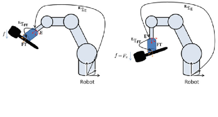
Fig. 5.1 Idea of FT sensor calibration. The FT sensor measures in its own coordinate frame FT.
Therefore, a transform
E
T
FT
from the end effector E to FT is required. a For any given robot end
effector orientation
R
T
E
, the tool's gravity force f acts. b If the sensor is vertically aligned, f acts
only in the z-component of the measured force
sample i we record the forces F
i
¼ð
f
x
i
;
f
y
i
;
f
z
i
Þ
and the end effector orientation
R
T
ð Þ
i
with respect to the robot's base R. In this case, we use R as the world
coordinate frame.
Let f be the magnitude of the measured forces. As the weight of the rigid tool is
constant, for perfect recordings the following equation applies:
2
;
f
¼
F
i
8
i
2
1
;
n
½
:
ð
5
:
6
Þ
Subsequently, we define the zero force F
0
as the force that impacts on the sensor
when vertically aligned (cf. Fig.
5.1
b):
0
@
1
A
:
0
0
f
F
0
¼
ð
5
:
7
Þ
Therefore, for any force recording F at a given end effector orientation
R
T
E
the
following relationship holds:
E
T
FT
F
¼
R
T
E
1
F
0
: ð
5
:
8
Þ
It says that the recorded forces F, after transformation into the effector coordinate
frame using the transform
E
T
FT
, are equal to the zero force F
0
transferred into the
current end effector orientation applying
R
T
E
.
Hence, we use the n recordings to transfer Eq. (
5.8
) into a (overdetermined)
system of linear equations to solve for the elements of
E
T
FT
. For an accurate
estimation of
E
T
FT
, we take at least n
¼
500 recordings. As the sensor to robot end
effector calibration is only required once (as long as the sensor is rigidly mounted
to the end effector), this calibration step is not time critical.
Note that we assume that the robot is horizontally aligned. If this is not the case,
an additional rotation matrix, which compensates for the skew position, must be
Search WWH ::

Custom Search