Biomedical Engineering Reference
In-Depth Information
4.2.1 Basic Idea of Online Calibration
As previously adumbrated, we mount a passive marker tool to the robot's third link
(cf. Fig.
4.2
). This marker consists of three reflective spheres that span a coordi-
nate system M. This coordinate system has a rigid transform to the coordinate
system that is in the robot's fourth joint (third link) S
3
:
S
3
T
M
¼
const
:
ð
4
:
1
Þ
Note that this equation merely holds as long as the marker is rigidly attached to
the third link. We use this constant transform to calibrate the robot to the tracking
system while tracking the marker M and calculating the position of the robot's
third link S
3
with the specific robot parameters applying the forward calculation to
joint 4 using the Denavit-Hartenberg (DH) convention [
6
]. This idea is schemat-
ically illustrated in Fig.
4.4
.
4.2.2 Marker Calibration
For estimating the constant transform
S
3
T
M
we use the QR24 algorithm for hand-
eye calibration (see
Sect. 4.1
or [
8
]). Instead of using a marker that is mounted to
the end effector, we use the marker M at the robot's third link. Accordingly, we
use the position of S
3
instead of the end effector position E. As the marker is
attached to link three, the marker movements consist of three Degree of Freedom
(DOF). As discussed by Strobl and Hirzinger, a full calibration can still be per-
formed with only three DOF [
22
].
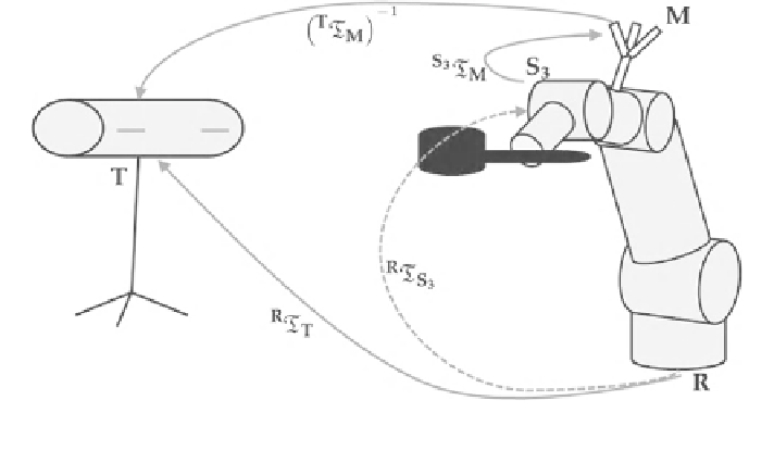
Fig. 4.4 Setup for the new calibration method: With a constant transform from the marker to the
third robot link, we can calibrate the robot to the tracking system with the robot forward
calculation and tracking the marker
Search WWH ::

Custom Search