Biomedical Engineering Reference
In-Depth Information
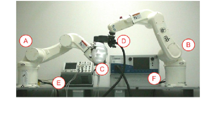
Fig. 2.6 Setup of the movement retrace based on two identical industrial robots: The first robot
R
1
(A) replays the recorded head motion holding a head phantom (C) and the second robot R
2
(B) carries the TMS coil (D) for the robotized TMS application. An Oscilloscope (E) measures
the induced electric field and the TMS coil is connected to a TMS stimulator (F)
A standard MCF-B65 figure-of-eight coil connected to a MagPro X100 stim-
ulator (MagVenture A/S, Farum, Denmark) generates the induced electric fields.
The TMS stimulus strength is set to 50 % of Maximum Stimulator Output (MSO).
A computer sends trigger pulses at about 1 Hz to the stimulator and reads the
measured voltages induced in the sensor from a digital oscilloscope (Agilent
Technologies, Inc., Santa Clara, CA, USA).
2.2.3 Typical TMS Scenarios
We use the recorded head motion to measure stimulus intensity for different TMS
scenarios. For this, we combine the head movements with 2 types of coil posi-
tioning: hold uses a static coil holder, and robot uses robotized TMS with active
motion compensation. In this way, besides evaluation of the recorded scenarios,
we also investigate the impact of head motion restriction on the motion com-
pensated TMS system. Hence, the following scenarios are used:
1. hold-and-restrain: Coil holder and avoiding head motion,
2. hold-and-rest: Coil holder and head rest,
3. robot-freely: Robotized TMS with motion compensation (MC),
4. robot-and-restrain: Robotized TMS with MC and avoiding head motion, and
5. robot-and-rest: Robotized TMS with MC in combination with a head rest.
To this end, we replay head motion from restrain for hold-and-restrain and robot-
and-restrain. For hold-and-rest and robot-and-rest we use head motion from rest
and we replay head motion from freely for robot-freely. Note that we cannot
Search WWH ::

Custom Search