Biomedical Engineering Reference
In-Depth Information
active joints. The system is therefore redundant with seven Degrees of Freedom
(DOF). The first subsystem consists of three rotational joints. In this way, the
system provides coil positioning around the head. The second subsystem consists
of a single joint which aims for the control of the coil to head distance. The third
subsystem consists again of three rotational joints acting as a serial wrist. This
allows to rotate the coil around the coil's center in all three spatial axes [
42
].
Figure
1.6
shows the setup of this robot.
Even though this setup allows for additional safety, e.g. in case of power
failure, the robot velocity, the maximum power and maximum torque of the
actuators are limited for optimized system safety [
89
]. Therefore, the maximum
coil velocity is limited to 6 mm/s [
89
]. The maximum force threshold is 2.5 N for
the force applied to the head [
42
]. Furthermore, due to the system setup, the
workspace is limited. For instance, the translational range of the second subsystem
is 80 mm [
89
]. As a result, the robot can only compensate for small and slow head
movements. The maximum distance to compensate for head motion during
stimulation and initial positioning errors is denoted with 50 mm [
89
]. However,
translational head motion during TMS can be up to 100 mm with a maximum
velocity of more than 80 mm/s as demonstrated with a systematic analysis of head
robot design.
Furthermore, a custom-made coil is integrated into the system, which makes the
system inflexible for usage of different TMS coils in TMS research. Nevertheless,
the coil is equipped with a grid of tiny force sensors, embedded in the coil's rear
side [
41
]. This allows for simple contact pressure control during a TMS session.
However, positioning the coil by hand is not possible.
In summary, this robotic TMS system is specifically designed for the purpose of
TMS. Safety is the key point of this system but with the cost of inflexibility. As the
TMS coil is a part of the robotic system, a coil change is hardly possible.
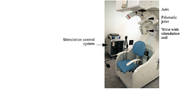
Fig. 1.6 Setup of the
specialized TMS robot. It
consists of a c-shaped robot
arm for coarse positioning. A
prismatic joint between wrist
and c-arm controls the
distance of coil to head. The
TMS coil is integrated in the
wrist which is responsible for
the precise positioning/
rotating of the coil. 2012
IEEE. Reprinted, with
permission, from [
89
]
Search WWH ::

Custom Search