Biomedical Engineering Reference
In-Depth Information
(a)
(b)
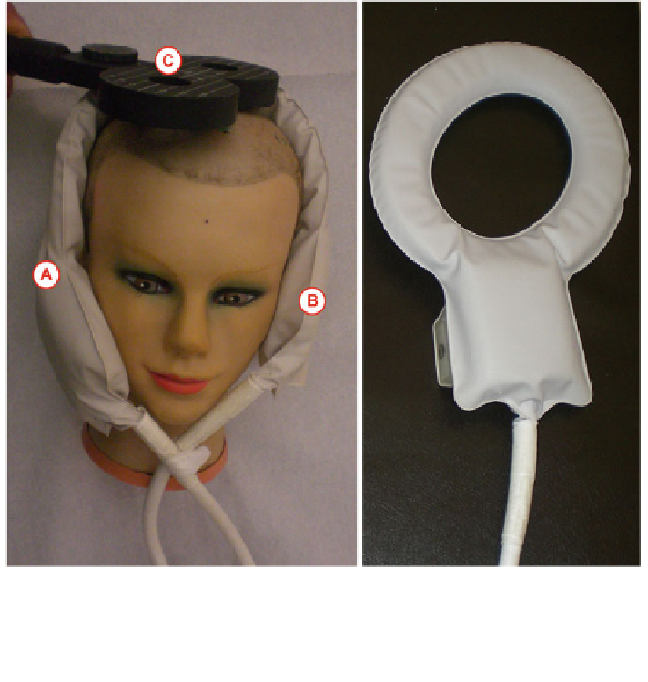
Fig. 10.2 Flexible surface head coil C3 (Philips N.V., Amsterdam, The Netherlands) used for
(f)MRI placed on a head phantom. a The head coil consists of two loops (A) and (B) that are
placed around the subject's head. In this way, areas of the scalp are left open (not covered by the
head coil). At these targets a TMS coil (C) can be placed for stimulation. In the shown case,
roughly M1-HAND is targeted with a C-B60 coil. b Single loop of the head coil
Even though, this setup does not allow to measure the changes in BOLD activation
simultaneously to the TMS pulse, it allows to measure the direct effect of a TMS
pulse or a train of pulses on the neuronal activity [
3
].
Currently, most TMS equipment manufacturers provide fMRI-capable TMS
coils and stimulators. However, positioning of the TMS coil on the subject's head
in the narrow environment of the MRI scanner is a very complex task. For fMRI
scans typically a specific head coil must be used for image recording. This further
limits the volume for coil handling as illustrated in Fig.
10.2
. However, by using a
flexible surface head coil consisting of two independent loops, areas of the scalp
are left open which can be used for TMS coil placement.
Bohning et al. introduced a coil positioning and holding system for interleaved
TMS/fMRI applications [
6
]. It consists of a pneumatic device with 6 Degrees of
Freedom (DOF) which allows the user to manually move the TMS coil on the
subject's head. After positioning, the holder maintains the coil at its spatial pose.
Search WWH ::

Custom Search