Biomedical Engineering Reference
In-Depth Information
250
B
A
200
Steel Ball
PyC
150
PyC/graphite
interface
100
Graphite
Rigid backing
Flexible backing
PyC/graphite
interface
50
PyC
0
0
100
200
300
400
500
Load, Newtons
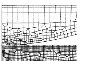
Fig. 3.1.3-8 FEA of indentation tests on PyC. (A) Part of the FE mesh showing a steel ball in contact with a PyC/graphite material.
(B) Maximum principal stress on the PyC surface adjacent to ball contact radius. (Reproduced with
permission from Gilpin et al., 1996.)
FEA was used to evaluate the stresses resulting from
a range of loads. The geometry was taken to be axisym-
metric, PyC was assumed to be an elastic material and
quadrilateral solid elements were used.
Figure 3.1.3-8A
shows part of the FE mesh. Note that the mesh is refined
in the contact areas but gets progressively coarser toward
the noncontact areas.
Figure 3.1.3-8B
shows the maxi-
mum principal stress on the PyC surface adjacent to ball
contact, as a function of the indentation load. ''Flexible
backing'' is seen to greatly reduce the maximum principal
stress in this area. The FE results were correlated with
data fromexperiments and used to develop failure criteria
for contact stresses. This in turn provided criteria for
designing contact regions in pyrolytic heart valves.
velocities only in the upper part of the merged jet, and an
almost uniform paraboloid distribution near the outflow
region (
Fig. 3.1.3-9B
). Twin spiral vortices are generated
immediately downstream of the valve, in the sinus
region (
Fig. 3.1.3-9C
) and are convected downstream,
where they quickly die away by diffusion. Shear stress
along the surface of the valve is shown to be a maximum
in the vicinity of its leading edge (
Fig. 3.1.3-9D
). A
study such as this provides useful information on the
function of the valve
in vivo
.
Conclusion
The FEM is an approximate, numerical method for
solving boundary-value problems of continuum me-
chanics that are posed in differential or variational form.
The main advantages of the FEM over other numerical
methods lie in its generalization to three dimensions and
the relative ease in which arbitrary geometries, boundary
conditions, and material anisotropy can be incorporated
into the solution process. The same FE code can be ap-
plied to solve a wide range of nonrelated problems. Its
main disadvantage has been its complexity to implement.
Fortunately, the abundance and availability of commer-
cial codes in recent years and an emphasis on a
''black box'' approach with minimum user interaction
have reduced the level of expertise required in the
implementation of FEA to most engineering problems.
Numerical analysis of 3D flow
in an aorta through an artificial
heart valve
Three-dimensional transient flow past a Bj¨rk-Shiley
valve in the aorta is simulated by the FEM combined
with a time-stepping algorithm (
Shim and Chang,
1997
). The FE mesh is shown in
Fig. 3.1.3-9A
, com-
prising some 32,880 elements and 36,110 nodes. The
results indicate that the flow is split into two major jet
flows by the valve, which later merge downstream. A 3D
plot of velocity vectors show large velocities in the upper
and lower jet flow regions in the sinus region,
large