Biomedical Engineering Reference
In-Depth Information
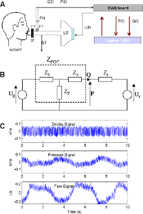
Fig. 3.1
A schematic
overview (
A
)andan
electrical analogy of the FOT
setup (
B
). Typical measured
signals (
C
) from one subject:
oscillatory driving air flow;
air pressure and air flow. The
breathing of the patient (low
frequency) can be observed
superimposed on the
multisine signals. Symbols:
LS
loudspeaker;
PT
pressure
transducer;
PN
pneumotachograph;
BT
bias tube;
bf
biological
filter;
U(t)
generated
pressure oscillations
(4-48 Hz);
P(t)
measured
pressure oscillations;
Q(t)
measured flow; pressure
unit conversion:
1kPa
10 cmH
2
O. See text
for further symbol
explanation
=
4-250 Hz. However, in this topic we will see applications of FOT over three differ-
ent frequency intervals: the low frequency range, from 0.01-5 Hz, mid-frequency
range, from 4-50 Hz and high frequency range, from 7-250 Hz. Due to limitations
implied by the loudspeaker, we have used two prototypes for the low frequency
range, described later in the topic. These prototypes kept the same principle of su-
perimposing oscillations on the tidal breathing of the patient, so they used the same
FOT lung function test.
The commercially available I2M (Input Impedance Measurement) device pro-
duced by Chess Medical Technologies, The Netherlands (2000) was used for pul-
monary testing. The specifications of the device are: 11 kg, 0
.
50
0
.
60 m,
8 s measurement time, European Directive 93/42 on Medical devices and safety
standards EN60601-1. Because the standard measurement time (8 seconds) is too
short, a second measurement line has been connected to a data acquisition card and
the signals recorded for 30-40 seconds, in order to provide better estimates. The
subject is connected to the typical setup as in Fig.
3.1
via a mouthpiece, suitably
designed to avoid flow leakage at the mouth and dental resistance artifact.
×
0
.
50
×