Cryptography Reference
In-Depth Information
ν
ν
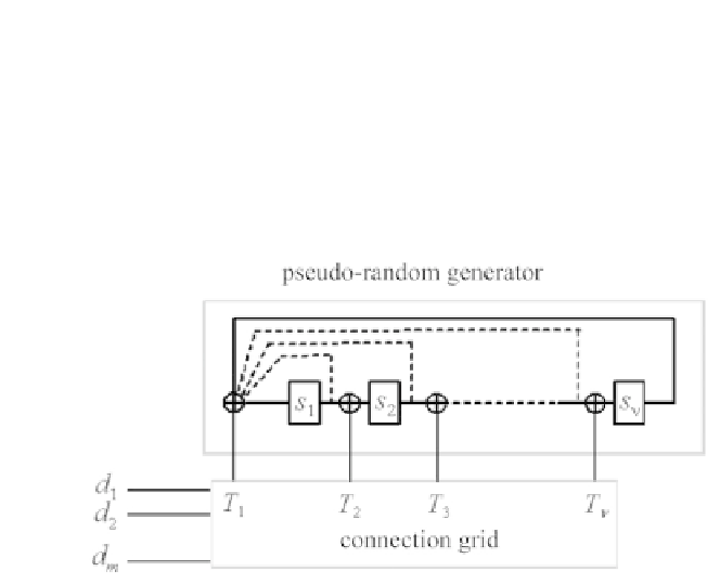
). The input vector
d
with
m
components is connected to the different
possible nodes thanks to a grid of interconnections whose binary matrix, size
ν
×
m
, is denoted
C
. The vector
T
applied to the
ν
possible taps of the register
at instant
i
,isgivenby:
×
T
i
=
C
.
d
i
(7.51)
with
d
i
=(
d
1
,i
...d
m,i
)
.
Figure 7.19 - General structure of an
m
-binary RSC encoder with code memory
ν
.
Thetimeindexisnotshown.
If we wish to avoid parallel transitions in the trellis of the code, condition
m
ν
must be respected and matrix
C
must be full rank. Except for very
particular cases, this encoder is not equivalent to an encoder with a single input
on which we would successively present
d
1
,d
2
,
≤
···
,d
m
.An
m
−
binary encoder
is therefore not decomposable generally.
The redundant output of the machine (not shown in the figure) is calculated
at instant
i
according to the expression:
y
i
=
j
=1
...m
d
j,i
+
R
T
S
i
(7.52)
where
S
i
is the state vector at instant
i
and
R
T
is the transposed redundancy
vector. The
p
-th component of
R
equals 1 if the
p
-th component of
S
i
is used in
the construction of
y
i
and 0 otherwise. We can show that
y
i
can also be written
as:
y
i
=
j
=1
...m
d
j,i
+
R
T
G
−
1
S
i
+1
(7.53)
on condition that :
R
T
G
−
1
C
≡
0
(7.54)
Expression
(7.52)
ensures,
first,
that
the
Hamming
weight
of
vector
(
d
1
,i
,d
2
,i
,
···
,d
m,i
,y
i
)
is at least equal to 2 when we leave the reference path