Graphics Reference
In-Depth Information
a
b
I
2
P
1
P
3
P
0
P
3
P
1
I
2
P
0
CRA
RADL
CRA
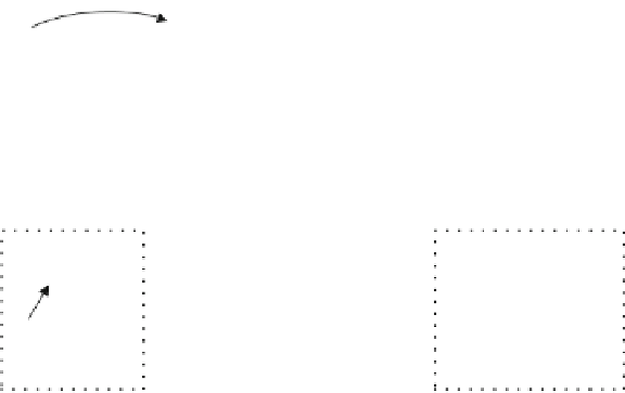
Fig. 2.7
Examples of disallowed referencing structures
a
b
B
2
B
4
B
12
B
14
B
16
RASL
P
0
P
1
I
3
P
10
P
11
I
13
P
15
CRA
CRA
Fig. 2.8
Original (
a
) and new (
b
) referencing structures before splicing has occurred
disallowed by this constraint is shown in Fig.
2.7
bsinceP
1
precedes I
2
but follows
P
3
in output order. If this referencing structure was allowed and random access was
made at the CRA picture, the missing P
1
picture would cause uneven output.
The third constraint is that all RASL pictures must precede any RADL picture
in output order. Since RASL pictures are discarded at random access but RADL
are not, any RASL picture that would be displayed after a RADL picture could
otherwise potentially cause uneven output upon random access.
2.2.2.9
Splicing and Broken Link Access (BLA) Pictures
Besides using a CRA picture for random access, it is also possible to use a CRA
picture for splicing video streams—where a particular IRAP access unit and all
subsequent access units of the original bitstream are replaced by an IRAP access
unit and the subsequent access units from a new bitstream. The CRA picture is the
most compression efficient IRAP picture type so splicing at CRA picture positions
may be the most common splicing case.
Figure
2.8
a shows an example original bitstream before splicing where the
pictures preceding the CRA picture in the bitstream have been highlighted by a
dotted box. Figure
2.8
b shows an example new bitstream where the IRAP picture
and the pictures that follow it in the bitstream are highlighted.
If the CRA picture is followed by RASL pictures, the RASL pictures may not be
decodable after splicing since they may reference one or more pictures that are not in
the resulting bitstream, e.g. the picture P
11
in Fig.
2.8
b. The decoder should therefore
not try to decode those RASL pictures. One way to prevent the decoder from trying